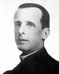
As the 100th anniversary of the first radio broadcasts in Brazil approaches, Landell de Moura's work once again comes to the fore, appearing in several articles and videos in the media.
However, what we notice in these works is that more is dedicated to the narration of the historical fact and its importance than to providing greater detail on the technology used by Landell and how he arrived at it.
We know that what Landell did was not exactly create any new components or use technology that was completely different from what researchers in other countries used. Landell improved what existed and introduced innovations that completely differentiate it from what previously existed,
As was the case at a time when there was no internet, radio or TV that allowed the immediate dissemination of information, Landell maintained correspondence with several researchers in Europe and even went on trips under the sponsorship of the Church to improve his inventions. He even traveled to New York where he set up a laboratory from which he patented his discoveries.
But what was the technology that Landell de Moura actually used to create the first transmitter capable of transmitting the voice, as what had previously existed was the transmission of telegraphic signals?
At that time there were no active elements such as tube or transistors to generate high frequency signals that, when applied to an antenna, would produce electromagnetic waves.
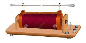
The technology was still that of Hertz who discovered electromagnetic radio waves, using a spark coil or Ruhmkorff coil. This coil, as shown in figure 2, was nothing more than a high voltage transformer which, fed by a low continuous voltage, generated a voltage high enough to produce a spark between two tip electrodes.
This spark was rich in high frequency harmonics, thus obtaining a current that, applied to an antenna, generated radio signals. The simplest way to capture these signals was the one used by hertz and shown in figure 3.
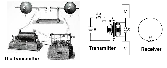
A ring formed an antenna and at its ends there were two small spheres separated by a fraction of a millimeter.
By capturing the signal at a distance that depends on the power of the transmitter, a voltage was induced and thus a small spark was produced between the spheres. These sparks were perfectly visible, proving that the signal had been captured.
The transmitted signal consisted of a damped oscillation rich in harmonics and at the beginning there was not even a concern with its tuning.
Over time, the transmitter was improved with the use of resonant circuits to obtain the concentration of signals at certain frequencies and also the search for a better way to detect the signals in a receiver.
Figure 4 shows the diagram of a typical spark transmitter of the time, from which Landell carried out his experiments.
The Ruhmkorff coil consisted of a vibrator, very similar to those used in old cars to generate high voltage in valve circuits. In figure 5 we see how this coil works.
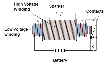
This coil worked as follows. When the low voltage winding was energized, its magnetic field immediately attract the contacts that were in series opening them. With this, the current was cut, the field ceased, and the contact returned to its normal position. When it returned to normal, it closed the circuit again, which was then energized by pulling the contacts and turning off the current.
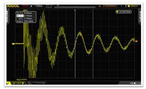
As a result, the contacts oscillated, opening and closing the contacts quickly, generating a pulsating current in the coil. This current induced a high voltage in the secondary. Applied to electrodes (sparker), it produced a spark between them. This oscillating spark was responsible for generating a radio signal if applied to an antenna. It can be seen that there was a damped oscillation given by the inductance of the coil and possibly an external capacitor. Due to the number of harmonics generated, the signal was actually composed of many parasitic frequencies. In figure 6 we have the waveform of the generated signal.
To receive the signals, several techniques were soon developed. The first detectors appeared that were based on substances that had the properties of forming semiconductor junctions.
For example, researchers at the time soon discovered that certain materials in contact formed these junctions, creating the most diverse types of detectors. Wires in contact with liquids, filings, crystals and even living creatures were used, such as an interesting detector using a frog's leg that we talked about in an article.
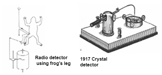
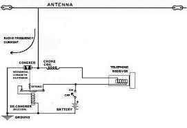
But the most popular at the time were the Branly coherer and the galena detector. The coherer, as Landell used in the receiver, consisted of a small glass tube filled with metal filings, as shown in figure 8.
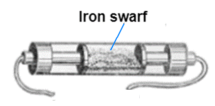
The swarf in poor contact did not conduct current and the device remained open. However, in the presence of the voltage induced when a radio signal was tuned, the swarf particles became conductive due to their proximity and the current passed. The coherer then conducted the current making its detection.
A headphone could then be connected to the circuit resulting in a receiver, as shown in figure 9.
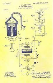
We can then start from Landell's patent to analyze the operating principle of the transmitter used. This patent is shown in figure 4 at the beginning of the article.
A prototype assembled by Landell's admirers, whose photo can be found on the internet, is shown in figure 10.
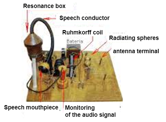
We then have a Ruhmfoff coil connected to a spark gap and an antenna circuit that generated the signals to be transmitted. We then have in the circuit the difference that made Landell an innovator: the microphone.
Landell used a microphone to modulate the signals. This curious microphone that can be seen in the figure consists of a coil that, due to the presence of sound waves, affected the frequency of the transmitted signals. We spoke through a tube and the sound fell on a diaphragm.
If we analyze this microphone we can say that he was also the inventor of the first dynamic microphone.
In this way, the signals emitted by Landell de Moura's spark transmitter were modulated and the speaker's voice could be clearly heard in the receiver.
Experiments with this equipment were carried out from 1882 onwards when it transmitted signals from Colégio São Luiz on Avenida Paulista in São Paulo to the Seminário de Santana in São Paulo at a distance of approximately 8 km.
I recently posted a post on Facebook in which I talk about my first spark transmitter that used something similar, but without the high voltage coil, but which interfered a bit with the neighbors' radios....
Electronic and radio transmission technology has evolved a lot since then, especially since the arrival of valves, but many curious things can be mentioned since then.
We can cite the time when transmitters were nothing more than mechanical generators (dynamos) that rotated so quickly that currents of hundreds of kilohertz could be applied directly to an antenna to produce radio signals.
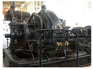
The carbon microphone was simply sandwiched between the very high voltage generator and the antenna to modulate the signals! Poor announcer if he accidentally touched the microphone energized with thousands of volts...
ART5156


