

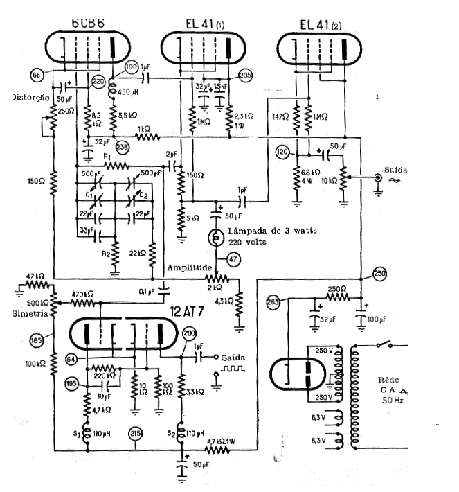
The circuit shown in the figure was obtained from a 1967 documentation. This generator generates sine signals that depend on R1, R2, C1 and C2. The signals are sinusoidal and the critical component, in addition to the tubes, is the power transformer which has windings for 100 mA or more.
The circuit also has a rectangular signal output which is obtained thanks to a gyroscope circuit with one of the valves. Note that the signal strength has a control and the maximum frequency obtained is of the order of 1 MHz with values of R1 around 4k and R2 around 560 ohm.
| Haga click en la imagen para ampliar |


