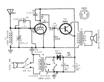
This circuit was found in a 1963 US publication translation. In the original version it uses a loop antenna, but we can employ a ferrite antenna made up of 100 loops of wire 28 on a 15 to 25 cm long pole. The grid resistor erased on the image scan is 10 M ohms. The transistor may be the BD136 and the output transformer is of the type found on transistor radios. R2 adjusts the volume and the variable capacitor can be obtained on old valve radios. The power transformer has a 12 V x 1.5 A secondary.