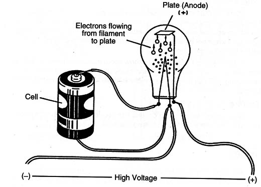
A vacuum exists inside a glass tube with some electrodes. In the case of a diode, a tungsten filament is placed inside (in some cases near an electrode called a cathode). Also nearby (without touching) is another electrode called an anode. To put the tube to work a positive voltage is applied to the anode, the cathode is connected to a negative voltage, and the filament is heated by a low-voltage source as shown in Figure 1.

When the filament and cathode are heated, electrons are emitted causing current flows between the filament (cathode) and the anode. If the anode is negative and the filament is positive no current can flow across the tube. In a tube like this, the current can flow only in one direction, such as in a semiconductor diode.
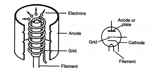
If we now place a metallic grid (Figure 2) between the anode and the cathode we can observe new electrical properties in the device.

A voltage applied to this grid can control the electron flow between cathode and anode. For example, if the grid is made negative the electrons are repelled and no current can flow. On the other hand, if the grid is made positive, the electrons are attracted and accelerate to the anode.
The amount of current between anode and cathode can be controlled with precision by the voltage applied to the grid. This device, called a triode, can be considered as an equivalent of the transistor and is used for the same purposes-as a switch or an amplifier.
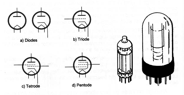
New tubes were developed from the triode configuration by adding new internal elements. The tetrode (four elements), pentode (five elements), hexode (six elements), and heptode (seven elements) are all examples of tubes that can be found in old equipment like radio receivers, audio amplifiers and TVs.
Although the tubes are very efficient in some applications and even used in some of them until recently, they have some disadvantages when compared with the equivalent modern solid-state devices like transistors.
The tubes need to be heated to operate and this implies the consumption of large amounts of energy. Another problem is that all the heat can be transferred to the surrounding area.
The tubes also need high voltage for their operation. Although common solid-state transistors operate with low voltages ranging from 1 to 30 volts in typical applications, in the same applications, the tubes need voltages in the typical range between 150 and 800 volts! Portable equipment using tubes is almost totally impractical.
Symbols and Examples
Figure 3 shows the symbols for many types of tubes found in old equipment (and even some modern) and two examples.

In the old types found in some military equipment, metal enclosures replaced the glass and the multiple tubes containing more than one configuration inside a body (a triode and a pentode, for example).
Specifications
The tubes are identified by a part number. There are two main codes used in their specifications. One of the codes uses a number followed by a group of letters and another number. The first number is the filament voltage, or the voltage that must be applied to the filament to heat the tube.
The second and third figures indicate the specific function. For example, a 12AX7 is a double triode tube that has a 12 V filament.
Another way of identification is the European code, where a group of letters indicates the function of the tube and the final number the specific type. For example, the tube ECC83 is a double triode (CC) (equivalent to the 12AX7l).
The best way to identify each tube is by consulting a manual.
Where they are found
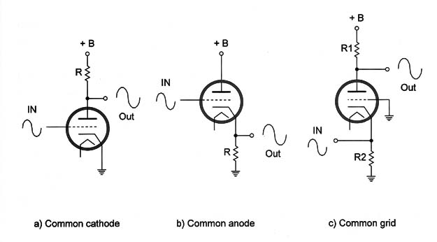
The reader will not often find tubes in modern electric installations. The tubes can be found in older electronic equipment, especially radios and TVs. The tubes can be used in the same configurations as the transistors, as shown in Figure 4.

Notice the tubes need, in addition to the low voltage to heat the filament, a high-voltage source for the anode. This high voltage ranges from 150 to 800 volts in common equipment.
Although in some cases it is not a good idea to try to restore old tube equipment, if you like it (perhaps for sentimental value), many dealers have all types of old tubes for replacements.
Testing
When the filament is open (burned out), the tube doesn’t function any more. In most of the cases, the malfunction of any piece of tube equipment is caused by this problem. The advantage of the tubes for the technicians is that it is easy to see if a tube is burned out because when the equipment is turned on, there is no orange or red light emitted by its filament. A visual inspection can reveal problems in this case.
But, this is not conclusive; some equipment exists where the filaments are wired in series. So, if one of them burns out, all the others are not powered and all the tubes are off.
A multimeter can be used to test the filament of a tube. The operational test needs special circuits or test equipment.


