Note: this project uses old technology, mas has the didatic and historic aspect. It was publublihed in one the magazines I worked in Brazil, and translated into Englishfor publication in one of my books.
Features
Power supply voltage: 117 Vac
Frequency range: 530 to 1,600 kHz
Distance range: up to half a mile
Number of tubes: 2
A very popular old tube receiver used in the 1960s and 1970s employed the 35W4, 12BE6, 12BA6, 6AV6, and 50C5 series of vacuum tubes.
Those old receivers, tuning the MW and SW band, used the tubes with filaments wired in series as shown in Fig. 1.

With this configuration, the receiver could be powered directly from the ac power line without the need of transformers, which were high-cost components at the time (and remain so today).
The filament voltage sum was 121 V - a little bit more than the power supply line voltage in some places 127 V as in Brazil.
So, with the use of a small resistor in series to add a voltage drop of a few more volts, the tubes could be heated directly from the ac power line.
In many such receivers, the resistor was inside the power cord (consisting of a resistive wire) so that when the receiver operated, the power cord was heated.
Because of this, these receivers were often referred to as heated tail radios.
Today, it is possible to find many of these old receivers abandoned, with the tubes still in good shape. If the reader can find these tubes (and the other components as well), an interesting MW transmitter can be built.
Using two of the tubes found in these receivers, we can build an “old-fashioned” transmitter that can send signals to MW receivers placed at distances of up to half a mile.
The 50C5 used in this transmitter can produce a 2 W signal, and the 12AV6 can modulate it with excellent performance.
The only problem is that the circuit is powered from the ac power line and has no isolation transformer.
Therefore, the reader must avoid shock hazards by installing the transmitter in a plastic or wooden box, and you must be careful when using it.
Suggested uses for this transmitter include the following:
It can be used as an experimental broadcasting station for schools, clubs, technology education, etc.
It may be useful for providing translation services in conference rooms. The translator can use this transmitter, and people who are interested in the service can hear him via the use of a small portable AM receiver with an earphone.
The transmitter can be used at the lab to perform experiments with plant growth and circadian rhythms. The plants can be submitted to the high-frequency fields produced by this transmitter.
Warning: It is important for readers to be aware that this transmitter can send high-power signals over long distances, so legal restrictions on its operation must be observed.
Use only a small antenna.
It is best to use it in locations that are far removed from populated areas and any other places where you might interfere with the operation of licensed communication equipment.
How It Works
Two tubes are used to this project. One, the 12AV6, is an audio triode intended to operate as an audio preamplifier, and the other, a 50C5, is a power pentode intended to drive a loudspeaker through a high-impedance transformer.
These tubes can be found in old radios and service shops.
Many dealers have them available either in stock or via special order.
Keep in mind that, if you obtain these tubes from an old radio, other parts can also be reused, such as the tube sockets and the variable capacitor.
Figure 2 shows a variable capacitor as used in old tube radios that can be used for our transmitter.
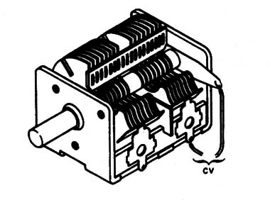
This is a two-section variable capacitor and it is important to make sure that the mobile plates don’t touch the fixed plates when the device is operated.
If this occurs, the part will short out and be useless for this project.
The high-frequency oscillator is a Hartley oscillator using the 50C5.
In this circuit, the coil and CV (the variable capacitor) determine the frequency.
The feedback that keeps the oscillator running is given by the tape connected to pin 6. R5 biases the control grid and R6 the cathode.
Note that the tube is powered from a high voltage coming from the power supply.
Keep in mind that this circuit operates at voltages up to 150 V.
Therefore, you must take great care when working with the circuit when it is powered up, because there is a serious shock hazard.
The modulation signal is applied to the control grid of V2 by capacitor C4.
This signal comes from V1, the preamplifier for the audio signals.
The circuit is very sensitive, and medium- and high-impedance microphones can be plugged into the V1 input.
The power supply is formed by a diode that directly rectifies the ac voltage from the ac power line. The dc voltage is filtered by C1.
This is a double high- voltage electrolytic capacitor.
This component can also be found in old radios, but it is important to test it before using.
Electrolytic capacitors wear out with time and must be tested before you use them.
Figure 3 shows how to test an electrolytic capacitor using a 6 V lamp and a 6 V supply.
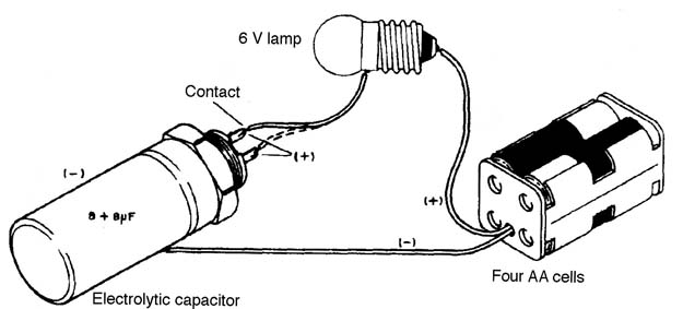
If the lamp glows in this test, indicating that the capacitor is shorted out, the capacitor cannot be used.
Of course this isn’t a definitive test. If the fuse opens when using this capacitor in your project, it is probable that the capacitor is the culprit.
You must replace it.
Assembly
Figure 4 shows a schematic diagram of the tube MW transmitter.
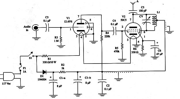
Thee circuit is mounted using a metallic chassis as shown in Fig. 5.
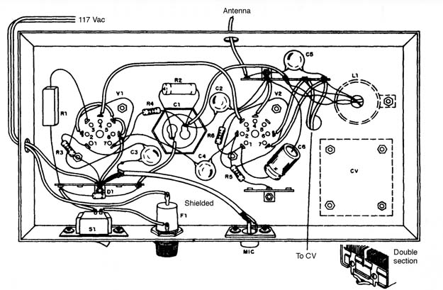
The holes for the tubes, transformer, wires, switch, fuse holder, and capacitor must be drilled before assembly.
It is important to have these components at hand, as they can vary in appearance and dimensions.
This allows the reader to make the alterations in the layout of the chassis according to the specific components used in the circuit.
After preparing the chassis, install the tube sockets, the transformer, and the variable capacitor.
For the variable capacitor, because the fixed plates are connected to ground in normal operation, we need to make some modifications to use the two sections as shown in Fig. 6.
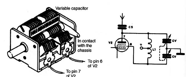
In this figure, observe the pointswhere the wires must be connected for correct operation.
The capacitor must have a plastic knob, as it is exposed to high voltages and can cause a shock if directly touched.
Two terminal strips are also fixed to the chassis to receive some small components and wiring.
Note that one terminal of each terminal strip is connected to the chassis, acting as a ground connection.
The audio input is via an RCA jack, and the antenna is a length of plastic-covered wire passing through a hole in the back of the chassis.
This wire is 6 to 10 ft long and will be placed in convenient position when the transmitter is used.
The recommended electrolytic capacitor is the type used for “chassis mounting” with a nut to fasten it in a hole.
When this capacitor is placed in the chassis, the negative pole (the case) is automatically connected to ground.
Any capacitor with values between 8 + 8 and 50 + 50 µF can be used for this project.
The voltage rate must be 200 WVDC or more.
Another important point to be observed in the mounting is that one of the power cord wires is connected directly to the chassis.
This means that the chassis is “alive” and can cause severe shocks if touched.
For this reason, the chassis must be installed in a plastic or wooden box.
The coil is formed by 40 + 40 turns of AWG 26 to 28 enameled wire in a 1 in. PVC tube.
You can also use a length of broomstick or plastic cable as a form.
The CT (central tap) in the coil must be connected using a short, shielded cable. The shield must be connected to ground (chassis) to avoid hum.
C2 is a ceramic capacitor with voltage rating of 500 V or more. R1 is a wire-wound resistor with a dissipation power of about 10 W or more.
Adjustments and Use
Install a fuse in the fuse holder and place the tubes in their sockets.
Observe the correct position for tube installation.
Place an MW receiver near the transmitter and tune it to a free point in the band.
The antenna wire can be placed at any convenient location.
Tum the transmitter power on and Wait two or three minutes while the tubes warm up.
The red light produced by the electrodes in the tubes is normal as is their high temperature.
Don’t touch the tubes while they are in operation, because they are very hot.
If the tubes don,t glow when the power is turned on, they are bad (blown) and can”t be used.
Next, by adjusting CV, you Will be able to tune in the signal. Plug a micro-
phone or other audio source into the input to test the modulation.
Waring: Any devwe plugged into the input will be exposed to the ac power line voltage. This means that you can use only plastic microphones with insulated cables or battery-powered devices as signal sources.
If a strong hum appears when you tune in the signaL turn the ac power plug 180°.
If the hum Continues, test C1. This Component may be defective.
To use this transmitter, you can use a mixer to transmit your Voice as well as music from a tape recorder or CD player.
Figure 7 shows an audio output transformer wired to allow the use of a small loudspeaker as a microphone.
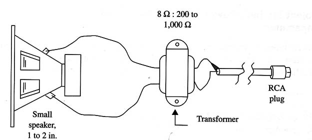
If the audio sources are powered from the ac line, use only supplies that incorporate effective isolation transformers.
Observe that the circuit also can be powered from 220 or 240 V power supplies if you incorporate an input transformer.
Tubes
V1 - 12AV6 audio triode, miniature tube
V2 – 50C5 audio pentode, miniature tube
Semiconductor
D1 1N4004 or 1N4007 silicon rectifier diode
Resistors (1/8 W, 5%)
R1 - 330 Ω X 10 W Wirewound
R2 - 1,000 Ω - 10 W Wirewound
R3 - 1,000,000 Ω -brown, black, green
R4 - 220,000 Ω -red, red, yellow
R5 - 470,000 Ω -yellow, violet, yellow
R6 - 330 Ω -orange, orange, brown
Capacitors
C1 - 8 + 8 µF to 50 + 50 µF, 200 WVDC or more, double electrolytic (see text)
C2- 0,1 µF x 250 V ceramic
C3, C4 – 0,1 µF x 50 V ceramic
C6 - 100 pF/400 V ceramic
C7 47 µF/35 WVDC electrolytic
Additional Parts and Materials
L1 - coil (see text) a
CV -double Variable capacitor (see text)
F1 - 1 A fuse and holder
S1 - SPST toggle or slide switch
Metal chassis, power cord, sockets for the tubes, knob for CV, plastic or wooden box, etc.


