Note: this project was included in my book Science Fair and Technology Education Projects published in USA.
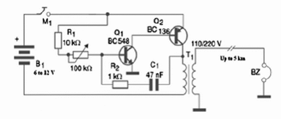
The long range project shown in figure 1 uses as transmitter an audio oscillator with a transistor and a step up transformer. The receiver is an earphone or even a small loudspeaker.

Range can be extended to 100 m, or more if a high impedance earphone is used. If a step up transformer is inserted in the circuit, like it was shown on the previous project and a piezoelectric earphone is used, the range can be extended to several kilometers.
In the one way version, the wires can be uncovered but they have to have isolators in the point where they are kept. The receiver is an earphone or a piezoelectric high impedance transducer (ceramic).
The transmission tone is adjusted by the potentiometer. The power supply consists in cells, a battery or an ACDC converter. Take care when operating the system since the voltage found in the transmission line is high and can cause some shock if it is touched.
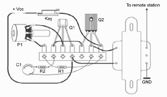
Figure 2 shows the placement of the components on a terminal strip, the simple solution for beginners.

Q1—BC548—General purpose silicon NPN transistor
Q2—BD136—Medium power silicon PNP transistor
T1—Transformer—primary 110/220 V—secondary—6 to 12 V x 200 to 500 mA
BZ—Piezoelectric transducer or high impedance earphone
B1—6 to 12 V or power supply—C or D cells
M1—Telegraphic key
P1—100 k ohm—lin or log potentiometer
R1—10 k ohm x 1/8 W resistor (brown, black, orange)
R2—1 k ohm x 1/8 W resistor (brown, black, red)
C1—47 nF ceramic or polyester capacitor
Other:
Cell holder, terminal strip, solder, wires, etc.
Competition:
The same as proposed in the previous projects.


