

Obs. This circuit is part of one of my books published in USA
Features
Power supply: 117 Vac
Frequency range: 530 to 1,600 kHz
Output RF power: 1 W (typical)
Modulation power recommended: 50 mW
Range: up to 120 ft
A signal repeater with a respectable output power, using the MW radio band, can be used in several interesting applications. The following are some suggestions for the reader:
When driven by the output of any audio system, the sounds can be transmitted to a receiver that is plugged into a remote audio amplifier. A wireless sound distribution system can be created in this manner.
Using the output of any small audio amplifier with a hidden microphone, the transmitter can send signals to a receiver in an adjacent room. In this way, conversations can be overheard at a distance.
Used with a tape recorder or mixer, the circuit can function as an experimental MW radio station for a school, club, or other organization. It can be used in science fairs to demonstrate how a radio station works.
The signal range depends on several factors. One of them is the presence of obstacles that can inhibit signal propagation. Walls and large metallic structures can block the signals. Another factor is the receiver’s sensitivity.
As in the MW band, the signals cannot carry over large distances. The average maximum distance for this project is 120 ft. This range can be increased if the ac power wiring is used as the antenna.
The circuit is very easy to build and has no critical adjustments. This makes the project ideal for beginners and students.
How It Works
A single transistor is used in a Hartley oscillator. The frequency is determined by CV1 and L1. CV1 must be adjusted to find a free point in the MW band between 530 and 1,600 kHz.
The feedback that keeps the oscillator running is provided by C1. R2 biases the transistor through P1. P1 also adjusts the amplitude of the modulating signal.
If the amplitude is very high, the signal peaks are chopped, causing distortion.
Therefore, the ideal adjustment point for this component depends on the power of the audio signal source.
The transformer is important for isolating the audio source circuit from the transmitter circuit, increasing security, and at the same time matching their impedances to obtain the best performance.
As the current drain is very high, a power supply that uses the ac power line is included with this project. This power supply uses a transformer with a primary winding rated to the 117 Vac power line (or 220/240 Vac, if this is the voltage where you live) and a secondary winding rated to 12 V CT, 1 A.
Capacitors C2 and C3 are used as filters. It is important keep all the wires short when building this circuit to avoid hums and instability. Special care must be taken with the length of the wire that is connected to CT in the coil.
Assembly
The circuit of the radio link is shown in Fig. 1.

As this is an experimental project, we suggest that readers who are less experienced with printed circuit board etching should use a terminal strip as the chassis.
Many variations of common terminal strips can be used. The components are placed on the terminal strip as shown in Fig. 2.

The coil is formed by 50 + 50 turns of AWG 26 to 30 enameled wire on a ferrite core 4 to 10 in. long. The diameter range is between 1/4 and 1/2 in. A suitable ferrite core can be found in old transistor radios.
For CV1, any variable capacitor with a capacitance range between 120 and 360 pF can be used. This component can also be found in old nonfunctioning transistor and tube radios. C1 and C2 must be ceramic capacitors, and C3 is an electrolytic rated to 25 WVDC or more.
For P1, any common linear or log potentiometer can be used. This component must be mounted appropriately so that the reader can use it to adjust the modulation.
The transistor must be mounted on a heat sink. Notice that if you use a 2N3055 or any equivalent in a TO-2 case, the terminal placement will be different from that shown, and the type of heat sink will also be different.
The reader should be alerted to the fact that a 2N3055 cannot oscillate at frequencies higher than 1 MHz, which will be important for some applications.
The circuit must be adjusted, when using this transistor, to a frequency between 530 and 650 kHz for best performance. The reader can use equivalents to the specified diodes such as the 1N4004 or 1N4007.
Many types of transformers can be used for this project. Any transformer with a high-impedance winding and a low-impedance winding (connected to R1) can be used.
For the prototype, we used a transformer with a 117 Vac winding (wired to P1) and a 6 V X 250 mA secondary winding (plugged to the audio input). R1 depends on the signal source. The following values are recommended:
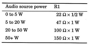
As many audio amplifiers are rated to PMPO (peak power) the correct value for R1 must be determined experimentally. A 20 W (PMPO) amplifier can in fact provide only 5 W (RMS) to a load.
Adjustments and Use
For experimental applications, the antenna is formed by a long piece of plastic-covered wire (6 to 20 ft) placed in a horizontal position as shown in Fig. 3.

You can also use the ac power line as an antenna. Connect the antenna terminal to the ac power line using a 0.01 14F x 400 V metal film capacitor. Try the two poles to see which one provides better performance.
When using the ac power line as the antenna, or even using a wire antenna if the receiver is placed near any wire connected to the ac power line (i.e., near outlets or light switches), the signal can be picked up easily.
Adjustment is easy: place any MW receiver near the transmitter and tune it to a free point in the MW band. Plug an audio source into the input of the transmitter and adjust CV to tune the signal.
Adjust P1 and the audio source volume control to get the best sound without distortion. The transistor will be warm in operation. This is normal.
Semiconductors
Q1 - TIP31, TIP3055, or 2N 3055 high-power NPN silicon audio transistor
D1, D2 - 1N4002 or equivalent silicon rectifier diodes
Resistors (1/8 W, 5%)
R1 - (see text)
R2 - 2,200 Ω -red, red, red
P1 - 10,000 Ω --potentiometer
Capacitors
C1- 0.022 µF ceramic
C2 - 0.1 µF ceramic
C3 - 1,500 µF/25 WVDC electrolytic
Additional Parts and Materials
T1 High-to-low-impedance transformer (see text)
T2 Transformer: 117 Vac primary winding; 12 V CT secondary winding rated to currents of 1 A or more
S1 - SPST toggle or slide switch
F1 - 1 A fuse and holder
Printed circuit board, power cord, plastic box, heat sink for the transistor, wire, antenna, ferrite core, solder, etc.


