

Features
Power supply Voltage: 3 to 6 Vdc
Range: 150 to 1,500 ft (see text)
Number of transistors: 1
I Frequency range: 470 to 650 MHZ
Current drain: 5 to 20 mA (typical)
One of the most important advantages of using a transmitter such as this one is that it doesn,t need an antenna. If an antenna is used to increase performance, it can be a Very short one.
Of course, the principal disadvantage is that you need a receiver that can tune in the µHF signals produced by this small transmitter. The suggested applications for this circuit are:
Short-range communications
Use as a wireless mícrophone
Espionage, to listen to conversations in adjacent rooms
Building the transmitter is very easy, as it uses common components. The critícal component is the coil, but the reader need not be intimidated by it, as it is incorporated in the printed Circuit board.
It is also recommended that you use a ñber printed circuit board, as high-frequency Circuits don,t work well with other material types.
How lt Works
The project is based on a common one-transistor oscillator in the common base configuration as described for many other projects in this book. L1 and CV determine the operational frequency.
CV must be adjusted to a free point of the µHF band that corresponds to the receiver frequency. As the coil is a Very low-inductance component, it is incorporated in the printed circuit board instead of installed as a separate component.
Thus, the half-turn coil Ll isn’t a real component in this project but a “virtual” component, as the reader can see.
The feedback that keeps the oscillator running is given by capacitor C3. This also is a homemade component. This low-capacitance device can be made using two pieces of common plastic-covered wire as shown in Fig. 1.

A length of wire as shown in the figure can form a 0.1 to 1 pF capacitor as required for this project.
The reader can use any transistor suitable for µHF operation such as the ones found in TV tuners and other sources. Types such as the BF689, BF970, BF979, and others can be evaluated.
Figure 2 shows the terminal layout for some of these transistors.

The modulation signal comes from an electret, two-terminal microphone. This component is very small and has an excellent sensitivity due an internal FET.
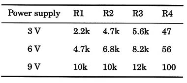
Resistor R1 is necessary just to bias the internal transistor, and its value depends on the power supply voltage. Current drain also depends on the power supply voltage.
Values between 5 and 20 mA are typical for this project. There are several suitable power supply options. Button cells up to 9 V batteries are acceptable as long as you change the values of some components as shown in the table below.
Assembly
A schematic diagram of the µHF transmitter is shown in Fig. 3.

The circuit must be mounted on a printed circuit board as shown in Fig. 4.

Special care must be taken with the coil, as any failure or other problem can affect the transmitter’s performance.
All of the capacitors must be ceramic types except C3, which can be a homemade version as described. The trimmer capacitor is a low-capacitance type, with its lowest capacitance at about 1 pF.
If trimmers with higher capacitance ratings are used, that will lower the transmitter frequency range, and it will be impossible to pick up the signal at the expected point. Notice in Fig. 4 that the lowest capacitance is obtained when the plates are in the position that provides widest separation.
An antenna is optional. If installed, it can be a piece of rigid plastic-covered wire no more than 4 in. long. The circuit can be installed into a small plastic box that includes the batteries.
Adjustments and Use
The reader must have a µHF receiver (scanner) that can tune frequencies in the range between 300 and 800 MHz. Tune it in a point between 470 and 650 MHz.
A µHF television set can also be used. With a trim adjustment, it is possible to pick up the transmitter’s signal in an audio channel located between channels 14 and 20.
Power the transmitter on and, using a nonmetallic tool, adjust the trimmer until you tune in the signal. As the circuit is very sensitive, any movement, or the presence of objects (e. g., your hand), can detune it. Install it in the box and make new adjustments.
When using the transmitter, don’t shake it or make quick movements, as the circuit again can be detuned.
Note that, if the circuit cannot be tuned to the desired frequency, you can adjust C3 by reducing the wire length or use a different trimmer capacitor (CV).
When using the circuit as a “bug,” install it away from metallic objects that can affect signal propagation.
Semiconductors
Q1 - BF689 or equivalent µHF NPN silicon transistor (see text)
Resistors (1/8W, 5%)*
R1- 2,200 Ω - red, red, red
R1 - 4,700 Ω - yellow, violet, red
R3 - 5,600 Ω - green, blue, red
R4 - 47 Ω - yellow, violet, red
Capacitors
C1, C4 - 0.1 1uF ceramic
C2 - 2,200 pF ceramic
C3 - 1 pF ceramic or home made (see text)
CV1 - 10 pF trimmer (see text)
Additional Parts and Materials
MIC - electret microphone, two terminals
L1 - coil, printed circuit (see text)
S1 - SPST toggle or slide switch
B1 - 3 to 9 V, cells, battery, etc. (see text)
Printed circuit board, battery holder or clip, plastic box, solder, Wires, etc.
Note: resistor values are for a 6 V version. See text for other voltages.


