Features
- Power supply: 6 Vdc
- Range: 300 ft
- Operation range: 88 to 108 MHz
This is a simple project that can be used for several purposes. Using a microphone as an audio signal source, it is possible to send coded messages to a remote receiver.
Anyone who tunes the signal will find it difficult to understand the message.
Another interesting use is to plug a guitar pickup transducer into the circuit to transmit the music, with special effects, to a remote receiver connected to a powerful audio amplifier. For readers who have already built experimental radio stations, this circuit can be useful for adding special effects to voice and music.
The circuit is powered from a 6 V supply (4 AA cells) and uses a low-power transmitter. However, the reader can replace the high-frequency stage With a high-power version, many of which are described elsewhere in this book.
How It Works
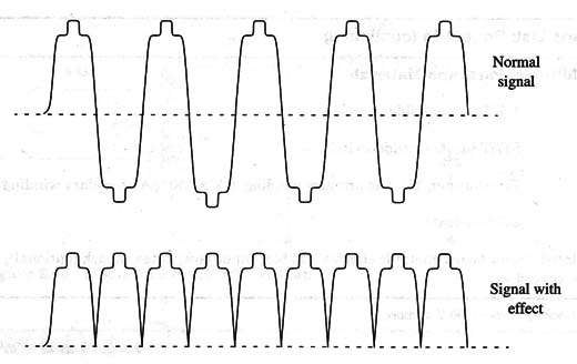
The secret of how the voice effect stage operates involves the use of a full-wave bridge that uses four diodes. This stage doubles the audio signal frequency and changes its wave shape.
The signal into this stage is picked up by a small transformer that also performs the function of isolating the circuit from the audio source. Figure 1 shows what happens when the audio signal is applied.

As we can see, the signal changes the wave shape and frequency, which means an alteration in the timbre if a voice or musical tone is used.
To drive the diode bridge, we need some power and a transformer to apply enough voltage to the diodes to break the voltage potential barrier found in the junctions.
So, to drive the bridge, an audio power stage was added. It is a four-transistor amplifier with an output of about 1 W. Of course, the reader can replace this stage with any audio output circuit, including modern versions using Ics such as the LM386, TDA7052, or TBA820.
The transformer must have one low-impedance winding to be driven by the amplifier output, and a high-impedance winding to drive the diodes. In the prototype, we used a power transformer with a 117 Vac primary winding and a 6 V x 250 mA secondary winding. The high-impedance winding is the 117 Vac primary, and the low-impedance winding is the 6 V secondary.
The transmitter stage uses a BF494 powered from a 6 V supply to reach distances up to 300 ft. The reader is free to use the transmitters described in other projects in this section of the site.
The trimmer potentiometer is used to get the best performance and least distortion with a particular audio source.
The “X” point indicated in the diagram is the audio output to the scrambler circuit. This point can be connected to the input of any audio amplifier or tape recorder. The antenna is a piece of rigid wire 6 to 20 inches in length.
Assembly
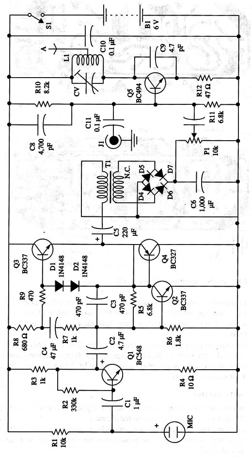
Figure 2 shows the schematic diagram of the transmitter.

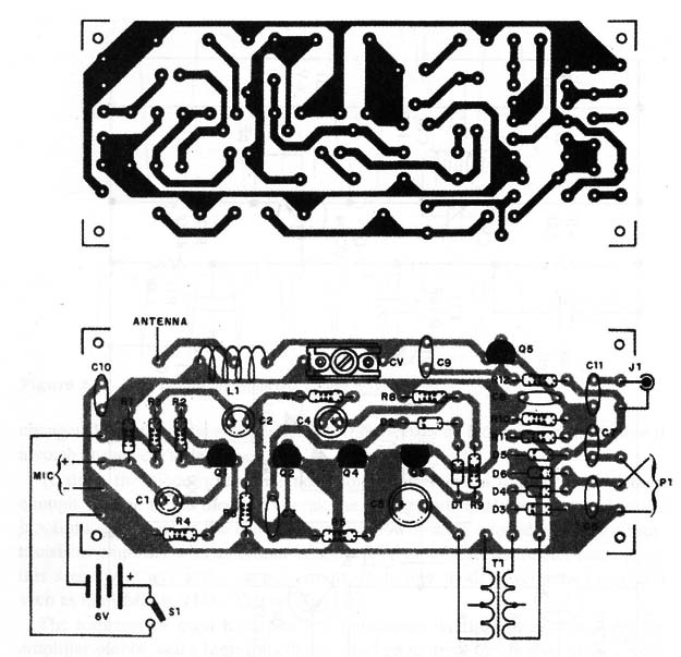
The printed circuit board used to mount the components is shown in Fig. 3.

Component specifications are given in the parts list. Notice that the capacitors used in the high-frequency stage must be ceramic plate or disc types.
CV is a trimmer capacitor with capacitance range between 2-20 and 4-40 pF.
The coil is formed by four turns of AWG 18 to 22 enameled or plastic-covered rigid Wire on a 1 cm diameter coreless form. You can use a pencil as a form for winding this coil.
It is necessary to place the cells in a battery holder. Take care when Wiring all of the polarized parts such as electrolytic capacitors, diodes, the transistor, and the battery holder.
For the audio signal input, use an RCA jack or other type appropriate for the audio source.
Adjustments and Use
Tune a receiver to a free point in the FM band and place it near the transmitter.
Adjust CV until you pick up the transmitted signal.
Speak into the microphone While you adjust P1 to tune your voice in the receiver with a high timbre. After these adjustments have been made, you can use the circuit as desired.
Semiconductors
Q1 - BC548 or equivalent general-purpose N PN silicon transistor
Q2, Q3 - BC337 or equivalent general-purpose N PN silicon transistors
Q4 - BC327 or equivalent general-purpose PNP silicon transistor
Q5 - BF494 or BF495 high-frequency N PN silicon transistor
D1-D5 - 1N4148 or IN 914 general-purpose silicon diodes
Resistors (1/8 W, 5%)
R1 - 10,000 ohm - brown, black, orange
R2 - 330,000 ohm - orange, orange, yellow
R3, R7 - 1,000 ohm - brown, black, red
R4 - 10 ohm - brown, black, black
R5, R11 - 6,800 ohm - blue, gray, red
R6 - 1,800 ohm - brown, gray, red
R8 - 680 ohm - blue, gray, brown
R9 - 470 ohm - yellow, violet, brown
R10 - 8,200 ohm - gray, red, red
R12 - 47 ohm - yellow, violet, black
P1 - 10,000 ohm - trimmer potentiometer
Capacitors
C1 - 1 µF/ 12 WVDC electrolytic
C2 4,7 µF/12 WVDC electrolytic
C3 480 µF ceramic
C4 - 47 µF/ 12 WVDC electrolytic
C5 - 220 µF/ 12 WVDO electrolytic
C6 - 1,000 pF ceramic
C7, C10, C11 - 0.1 µF ceramic
C8 - 2,200 µF ceramic
C9 - 4.7 pF ceramic
CV - trimmer (see text)
Additional Parts and Materials
S1 - SPST toggle or slide switch
MIC - electret microphone, two terminals
B1- 6 V, 4 AA cells
J1 - RCA jack (see text)
L1- coil (see text)
T1 - 117 Vac primary Winding, 6 V X 250 mA secondary (see text)
Printed circuit board, battery holder, plastic box, antenna, wires, etc.


