Obs. This project is part of one of my books published in USA.
Features
Power supply voltage: 6 to 9 Vdc
Range: 15 to 100 ft
Frequency range: 530 to 1,600 kHz
Oscillator: Hartley
Two transistorized stages are used in this transmitter to increase the output power. But because, in the MW range, it requires a great deal of power to send the signal over long distances, this project does not provide the same performance as equivalent ones operating in the SW or FM range.
It therefore can be used as an experimental radio station or link to send audio signals to distances only up to about 100 ft.
Several uses are suggested for a circuit like this. The applications are the same as described for similar projects as follows:
It can be used as a radio link to send signals from a tape recorder, TV, or audio system to a remote receiver or loudspeaker.
It may be useful as an experimental radio station for sending programs to radios placed around the school or home.
It can be employed as a secret listening device when combined with an amplifier and a microphone.
The circuit can be powered from 6 to 9 V power supplies. The supply can use single cells or a battery. If you use a supply that is fed from the ac power line, a 6 to 9 V X 500 mA rated type is recommended.
How It Works
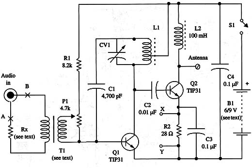
A high-frequency signal in the range between 5 30 and 1,600 kHz is produced by a Hartley oscillator using a medium-power silicon transistor. The signal frequency is determined by L1 and CV1. CV1 must be adjusted to a free point in the MW band.
This circuit performance is improved by a high-frequency amplifier stage. This stage uses another medium-power NPN silicon transistor and can increase the signal output to as much as 1 W.
Modulation is achieved by the aid of a transformer, as in the other MW amplitude modulated (AM) circuits described in this book. The transformer must match the audio system output impedance to the oscillator stage input impedance.
A potentiometer is used to adjust the correct signal level to be applied to the transistor base. This adjustment is necessary to find the best modulation without any distortion.
The second stage is a class C stage, where there is no resistor to bias the transistor. The transistor is biased by the charging and discharging process of C2.
This means that the transistor conducts only during one of the signal half-cycles.
As the load for this stage, we use a high-frequency choke. This means that the signal can be picked up from the second-stage collector.
The standby current for the second stage is given by R1 and R2. For R1, the reader can conduct experiments with resistors between 2,200 and 10,000 Ω to find the best performance.
We also include a second modulation input to the second stage. Low-impedance signals using a transformer can be applied at this point, modulating the signals. Using a transformer (4 or 8 Q secondary winding), the output of a small amplifier in the power range of 200 mW to 2 W can be connected to this point.
The reader is free to make many modifications in this circuit, such as:
- Alter R1 and C1 for better performance.
- Change R2 for better modulation.
Alter L1 according to the frequency.
Assembly
A schematic diagram of the two-stage MW transmitter is shown in Fig. 1.
As the circuit is not critical and is designed for students and beginners, the components can be mounted on a terminal strip as shown in Fig. 2.
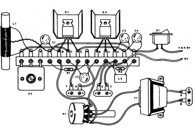
Of course, a reader who knows how to etch a printed circuit board may prefer that option, which allows the unit to be installed in a smaller box.
The coil is formed by 50 + 50 turns of AWG 26 to 30 enameled wire over a ferrite core 4 to 10 in. long. The diameter can be in the 1/4 to 1/2 in. range. If you have trouble finding AWG enameled wire, use common plastic-covered AWG 22 wire to wind the coil.
For CV, you can use any variable capacitor with capacitancesin the range between 120 and 360 pF. This capacitor can be found in old transistorized MW radios.
Avoid variable capacitors found in PM radios, as they are low-capacitance types.
L2 is a high-frequency coil with an inductance between 47 and 470 µH. You can create a home-made version by winding 200 to 300 turns of AWG 30 to 32 enameled wire on a 100 k!) X 1 W resistor.
Any transformer with a high-impedance primary winding and a low-impedance secondary winding can be used for modulation. In the prototype, we used a 117 Vac primary winding and 6 to 12 V secondary winding with current ratings in the range between 250 and 500 mA.
The low-voltage secondary is plugged into the audio input. You can also use a small audio output transistor as found in old transistor radios for this task.
The transistor must be mounted on heat sinks. The heat sinks consist of small pieces of metal bent to form a “U” and affixed to the transistors. A power supply for this circuit is shown in Fig. 3.
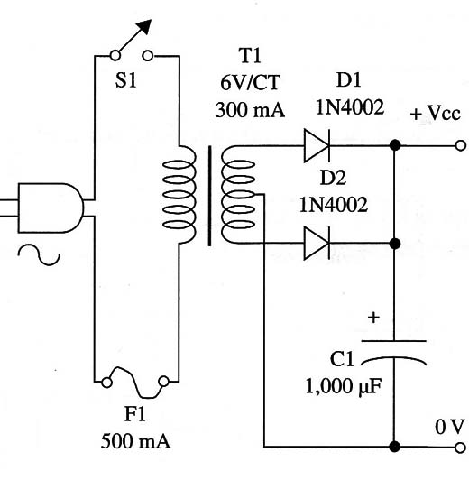
The transformer has a 117 Vac primary winding and a secondary winding rated to 6 V CT with currents of about 250 mA or more.
The electrolytic capacitor must be rated to 12 V or more, and you can use equivalents to the diodes. A terminal strip with screws is used to connect the antenna and the ground wire. If you intend to use cells, C or D types are recommended, as the current drain is high.
Adjustments and Use
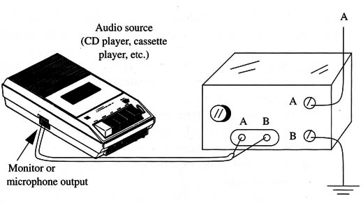
Figure 4 shows how the circuit can be used with a tape recorder or other audio source to send music to remote receivers.
If the reader intends to use the transmitter with an electret microphone, a small amplifier must be added as shown in Fig. 5.
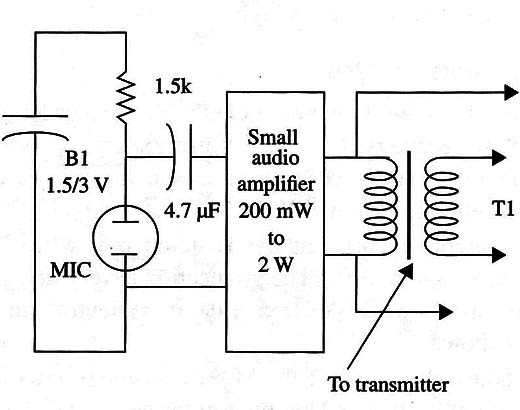
The amplifier should generate 100 mW to 1 W.
The antenna is formed using a piece of plastic-covered wire 6 to 30 ft long and wired as shown in Fig. 6.
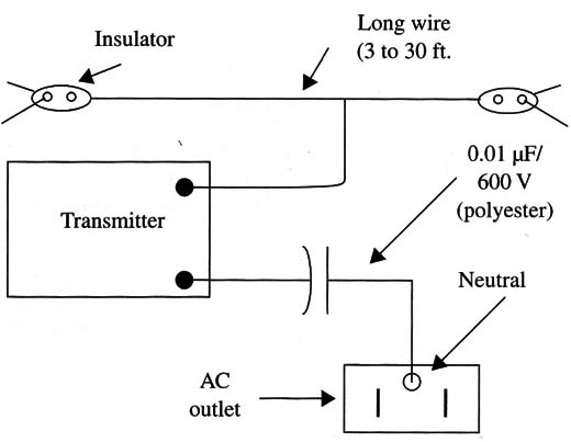
The ground connection is very important for increasing performance. This connection can be made to the neutral pole in the ac power line as shown.
To adjust the circuit, place the MW receiver near the transmitter and tune it to a free point in the band. Power up the transmitter and adjust CV1 to pick up the signal, and P1 to get the best sound reproduction without distortion. A tape recorder, CD player, or other audio source can be used for the adjustments.
Semiconductors
Q1, Q2 - TIP31 medium power NPN silicon transistor, any suffix
Resistors (1/8 W, 5%)
R1 - 8,200 Ω - gray, red, red
R2 - 22 Ω - red, red, black
P1 - 4,700 Ω - potentiometer
Capacitors
C1 - 2,200 µF ceramic
C2 - 0.01 µF ceramic
C3, C4 - 0.1 µF ceramic
CV - variable capacitor (see text)
Additional Parts and Materials
T1 - transformer (see text)
L1, L2 - coils (see text)
B1 - 6 to 9 V, cells or power supply (see text)
S1 - SPST toggle or slide switch
Terminal strip, plastic box, power cord (if necessary), components for the power supply, battery holder, ferrite core, knobs for the variable capacitor and the potentiometer, wires, solder, etc.


