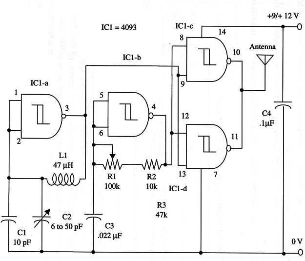
The high-frequency oscillator is controlled by Cl, and the audio-frequency oscillator is controlled by R1.
Using a short antenna (1 to 6 ft), the signals can be received in distances up to 10 ft.
Figure 1 shows the complete schematic diagram of the tone-modulated transmitter.

The Morse key is connected between the power supply and the positive rail of the transmitter. L1 can also be a home-made coil. It is formed with 40 turns of 24 or 26 gauge insulated wire on a ferrite rod, with the coil having a 1/8-inch I.D.
IC1- 4093 CMOS integrated circuit
L1 - 47 µH micro-choke
C1 - 10 pF ceramic capacitor
C2 - 6to 50 pF trimmer,
C3 - 0.022 11F ceramic or metal film capacitor
C4 - 0.1 µF ceramic or metal film capacitor
R1 - 100,000 ohm - potentiometer
R2 - 10,000 ohm, 1/4 W, 5% resistor


