Features
Power supply: 6 to 9 Vdc (four AA cells or a battery)
Frequency range: 7 to 15 MHz
Output power: 20 mW (typical)
This very low-power shortwave transmitter can be used to send signals to a receiver placed 3 to 20 ft away. This means that it can be used as a wireless microphone or for demonstrating basic radio principles, such as in a science fair or in technology education.
However, low power doesn’t necessarily mean that signals cannot carry over long distances. Low-power transmitters can send signals to receivers a thousand miles away when using appropriate antennas and under special propagation conditions.
Amateur radio operators can use these transmitters to test their skills in making contact with very distant radio installations. They often use transmitters in the range of 1 mW to 10 mW.
It is a test ofyour technical skills to try to send the signals produced by this small transmitter over the greatest possible distance.
How It Works
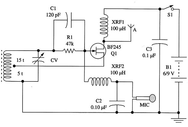
This circuit uses a Hartley oscillator with an FET. The frequency is determined by L1 and CV. CV adjusts the frequency to a free point in the shortwave range between 7 and 15 MHz.
R1 biases the transistor gate, and C1 applies the feedback signal to the transistor, which keeps the oscillator running.
For an experimental application, the signals are applied to a telescoping antenna 20 to 40 in. long. But, if the reader prefers, an external antenna can be connected to this point. In this case, it is important to establish a good ground connection to increase the signal propagation into space.
Figure 1 shows how a dipole or a long wire antenna can be used with this transmitter.
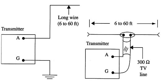
The modulation is given by a high-impedance (crystal or ceramic) microphone placed as shown in the figure. Unfortunately, this circuit cannot use other types of microphones without modification. As the circuit is intended as a portable and experimental unit, this configuration is suitable for the task.
Coil XRFl is used as a load for the RF signals.
Assembly
The circuit of the FET shortwave transmitter is shown in Fig. 2.
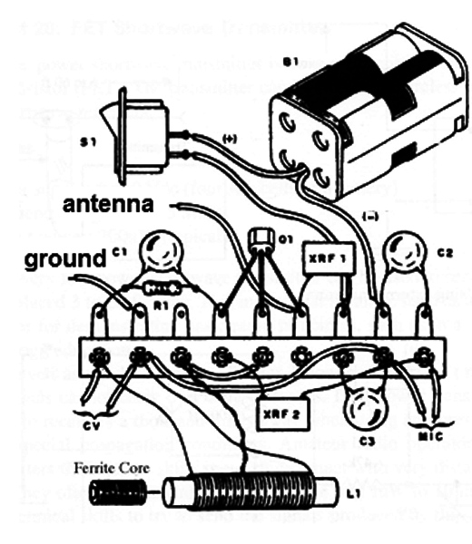
If you are a beginner or don’t have the resources to etch a printed circuit board, you can use a terminal strip as shown in Fig. 3.
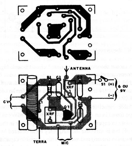
You can also mount the circuit on a printed circuit board. Figure 4 shows how the components are placed on it.
L1 is formed by 5 + 15 turns of AWG 26 to 30 enameled wire on a cardboard tube with a diameter of 1/4 in. Inside this tube, a small ferrite core must slide as shown in Fig. 5.
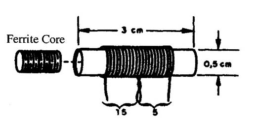
CV is a variable capacitor with capacitance in the range between 120 and 360 pF. Any type found in an old MW or SW transistor radio can be used.
It is also possible to experiment with a trimmer capacitor in the range between 2-20 and 3-30 pF. but in this case the frequency band covered by the transmitter will be as narrow as in the original version with a variable capacitor.
The original FET is a BF245, but equivalents such as the MPF102 can also be tested. The reader only has to pay attention to the terminal placement if an equivalent is used.
For instance, the MPF102 does not have the same terminal configuration as the BF245.
XRFl and XRF2 are RF chokes with values between 47 and 100 µH. But, as these components are not critical, a homemade component can be used. Wind 40 to 60 turns of AWG 30 to 32 enameled wire over a match or any plastic or card-board tube with a diameter of l or 2 mm and a length of 2 to 3 cm.
The microphone must be a crystal or ceramic high-impedance type. Four AA cells or a 9 V battery can be used as the power supply.
All the components can be installed in a small plastic box. The basic dimensions to this box depend on the version and the power supply you use.
Remember that a 9 V battery is smaller than four AA cells in a holder.
Adjustments and Operation
Tune a SW receiver to a free point in the band between 7 and 15 MHz. The receiver must be placed at a distance of l to 3 ft from the transmitter.
Power on the transmitter and adjust CV to tune the signal. At the same time, speak into the microphone to have a modulated signal to tune.
If your version uses an external antenna, connect it to the circuit and make new adjustments. The presence of an antenna can alter the frequency, requiring readjustment.
Be careful not to tune to a harmonic signal. The fundamental is the strongest one, and it can be tuned at the greatest distance from the transmitter. When using this as a portable unit, avoid shaking the antenna or touching components.
Semiconductors
Q1 - BF245 or equivalent JFET
Resistor (1/8 W, 5%)
R1 - 47,000 ohm - yellow, Violet, orange
Capacitors
C1 - 120 pF - ceramic
C2 - 0.01 µF - ceramic
C3 - 0.1 µF - ceramic
CV - variable capacitor (see text)
Additional Parts and Materials
MIC - Crystal or ceramic microphone (see text)
XRFl, XRF2 - 47 to 100 µF- choke
B1 - 6 V or 9 V, four AA cells or 9 V battery
S1 - SPST toggle or slide switch
Printed circuit board or terminal strip, battery clip or battery holder, antenna, plastic box, wires, solder, etc.


