

Obs. The article was originally published by Popular Electronics in 1998.
There are those who would say that the wireless communications hobby has gone the way of the dinosaur-and perhaps they’re right from a particular point of view, that is.
No one would dispute that the ranks of ham radio enthusiasts and DXers have been on the decline for some time now.
Even so, there are still plenty of communications enthusiasts out there searching for simple low-power FM transmitters.
This article, in catering to that all but forgotten segment of the electronics hobby presents a number of RF transmission circuits with which the hobbyist can experiment.
All of the circuits-which are composed of readily available components, powered from sources ranging from 3 to 9 volts, and capable of covering distances up to half a mile are tolerant of modifications, such as increasing the power or altering the frequency band or the modulation signal used.
One-Transistor FM Transmitter.
Our first transmitter circuit (see Fig.1) which is built around a single transistor is probably the simplest of its kind.
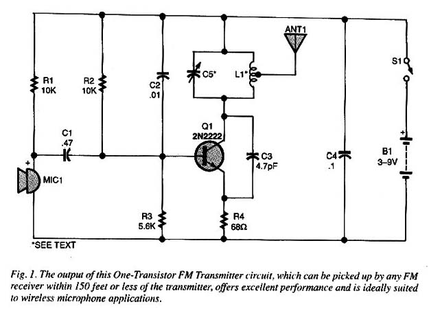
The signal transmitted by that circuit can be picked up by any FM receiver within 150 feet or less of the transmitter.
The circuit, which offers excellent performance, is ideally suited to wireless microphone applications.
As the Fig. 1 circuit lacks an audio amplifier stage, it’s necessary to speak directly into MIC1 inductor L1 is a hand-wound, air-core coil comprised of 4 turns of 18 to 22 AWG enameled wire wound on a 1-cm form.
The number of turns comprising L1 can be varied in order to produce a circuit that can output signals in the high VHF band (2 or 3 turns) or the low bond between 50 and 80 MHz (5 to 7 turns).
Operating In the low VHF band, the signal from the transmitter can be picked up on any VHF TV channel between 2 and 6.
Capacitor C6 can be any trimmer with a value ranging from 20 to 40 pF.
The transmitter, as shown, can be powered from a 3- to 6-Volt source.
However, if greater output power is desired, the circuit can be driven from a 9-volt battery-in that case, the value of R4 must be increased to 120 Ω.
The antenna is little more than a 4- to 15-inch length of bare wire, connected to the second turn of L1.
The wire antenna can be replaced by a telescoping antenna.
To use the circuit, simply tune your receiver to a tree point on the FM band.
Adjust C5 until you hear the signal from your FM transmitter.
Speak near the microphone to test the sound reproduction.
If carrying the transmitter to a position for from the receiver causes the signal to disappear, you’ve probably tuned a spurious signal or harmonic frequency.
In that case, readjust the circuit and try again.
Two-Transistor FM Transmitter.
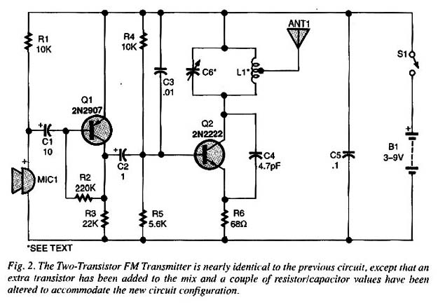
Our next transmitter, see Fig. 2, is nearly identical to the previous circuit, except that an extra transistor has been added to the mix and a couple of resistor/capacitor values have been altered to accommodate the new circuit configuration.
The inclusion of a single transistor in picked up and transmitted to a common FM receiver placed as far as 150 feet from the transmitter.
The microphone itself can be placed at the focal point of a parabolic reflector making it ideally suited to picking up very weak sounds emanating from a single direction.
Such a circuit might find application in surveillance operations.
Inductor L1 and antenna ANT1 in the Fig. 2 circuit are identical to the coil and antenna used in the Fig. 1 circuit, and like the Fig. 1 circuit this one can be powered from 3- to 6-volt sources with no modifications to the circuit.
In order to operate the Fig. 2 circuit from a 9-volt source, the value of R6 must be changed to 120 Ω.
That modifi- cation allows the output of this circuit to be picked up at distances of up to 600 feet when operating in an open field.
The transmission range diminishes considerably when the transmitter is operated from within a closed solid structure, such as a brick.
Tuning for this circuit is accompiished as if was for the previous transmitter.
To use the Fig. 2 circuit in spying applications, place the transmitter for from metal objects, such that the microphone has an unobstructed of the area that is being monitored.
Low-Impedance Transmitter.
The third circuit (see Fig. 3) is designed to use a low-impedance transducer as the pick-up device.
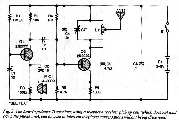
The transmission range for this circuit is the same as for the two previous transmitters, but offers some advantages over the prior circuits.
One of the advantages is that a small low-impedance speaker can be used as a microphone.
In addition, with a telephone pick-up coil attached to the telephone receiver (as shown in Fig. 4), the conversation can be fed to a receiver placed several feet away.
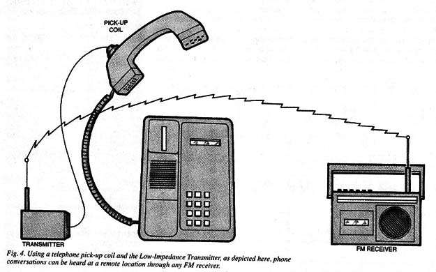
Since there is no direct connection to the telephone line with that arrangement, the transmitter won’t have a loading effect on the phone line.
When coupling the circuit to the telephone line in the manner outlined here, the telephone feed (the wire cable that connects to the telep hone base) must also be coiled, as illustrated in Fig. 5.
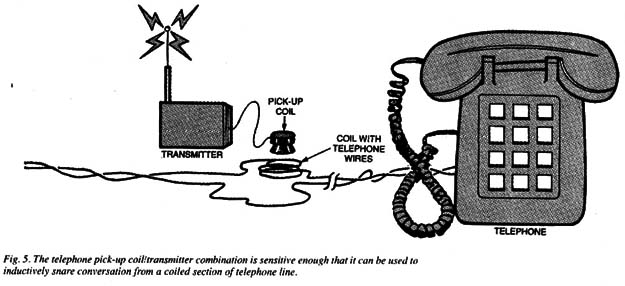
While the pick-up coil can be purchased from almost any electronic parts dealer, a home-brew unit can be manufactured by winding 1000 to 5000 turns of 30 or 31 AWG enameled wire on a small ferrite rod. inductor L1 in this circuit is the same as described in the previous circuits.
And like the other transmitter circuits, this one can be powered from a 3- to 6-voit source, with the 9-volt power source requiring that R6 be replaced by a 120 ohm resistor.
Also like the previous circuits, this one is tuned via a variable capacitor (C7).
If the received signal saturates the transmitter, causing it to output distortion-rich audio, it may be necessary to alter the value of R3, which can range from 22 Ω to 220 Ω.
Tone Transmitter.
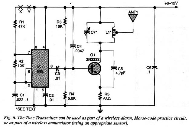
The Tone Transmitter circuit shown in Fig. 6 can be used as part of a wireless alarm, Morse-code practice circuit, or as part of a wireless annunciator (using an appropriate sensor).
Wired to a trap, the circuit can be used to alert you when the trap is sprung.
For example, to use the circuit as a remote temperature or light sensor, replace RT with a light-dependent resistor (LDR), or a negative-temperature coefficient (NTC) thermistor.
Regardless of the type of sensor selected, it should have the nominal resistance of between 10 k and 100 k.
In such an arrangement, the frequency of the output signal depends on the amount of light striking the LDR or the temperature sensed by the thermistor.
The sensor can be connected in the circuit at pointsX and Y.
The output frequency of the transmitter can be determined by connecting a frequency-counter to the output of an FM receiver.
The circuit generates an FM signal that’s modulated by an audio tone whose frequency is determined by Rt, R2, and Cl.
Inductor L1 is the some used in the other transmitters with circuit tuning accomplished in the same manner.
The Tone Transmitter has a range of between 150 and 600 feet in an open field when the circuit is powered from A AA-ceils.
The Circuit's output power can be increased (in order to provide greater transmission coverage) by powering the circuit from 9- or 12-voit DC supply.
To reconfigure the circuit for 9-volt operation, replace R5, 68-ohm resistor, with a 120-ohm unit .
If 12-volt operation is desired, replace Q1, a 2N2222 general-purpose NPN transistor, with a 2N221 8.
Those alterations allow the circuit to transmit over distances of up to a mile in an open field.
Caution: The FCC forbids operation of high-powered versions of a circuit like this one within city limits, where the signals can cause interference in emergency or other communications, FM receivers VHF TV.
Beep Transmitter.
The circuit shown in Fig 7 transmits intermittent beeps to a remote FM receiver.
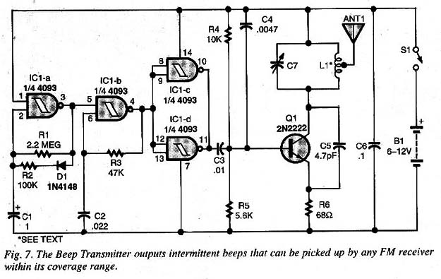
The pitch of the transmitted tones and the interval between beeps can be altered according to the application.
Resistor R3, which can range between 10k and 100k, determines the pitch of the tone, while the beep interval is determined by R1, whose value can range between look and 10 megΩ.
The Beep Transmitter can be used in a game named “Fox Hunt.”
The Transmitter is the fox and the hunters are those using FM receivers to locate the fox by the transmitted signal.
To increase the transmitter's coverage area, make the same modifications described for the Fig.4 circuit.
The circuit, when operated from a 12-volt supply, should be used only in an open field, for from radio receivers, so as not to interfere with their reception.
Light-Activation Circuit.
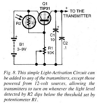
The simple circuit shown in Fig. 8 can be added to any of the transmitter circuits, except those powered from 12-volt supplies, allowing the transmitters to turn on whenever light level detected by R2 (an LDR) clips below the threshold set by potentiometer R1.
CD-Player/Muflimedia Transmitter.
The circuit shown in Fig. 9 allows audio signals from a PC or CD player to be sent to your FM sound system for reproduction through the system’s loudspeakers without the need for interconnecting wires.
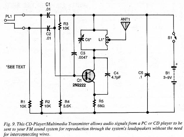
The circuit is monophonic, so the left and right channel audio signals are mixed in the transmitter circuit before being output to the antenna (ANTI) as shown in Fig. 9.
As there is no multiplexing of the signals, the receiver can’t reconstitute the left and right stereo channels.
The circuit can be powered from a 3- to 9-voit power supply.
For 3- to é-volt operation, no changes are necessary, but for 9-volt operation, the value of R4 must be increased to 120 Ω.
Field-Strength Meter.
Our final circuit, see Fig. 10, is a useful little circuit that can be used to indicate the strength of the signals output by any of the transmitters that we looked at here.
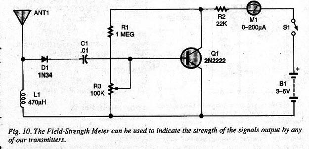
Potentiometer R3 (a 100k unit) is used to adjust the sensitivity of the circuit, by biasing the transistor near the point of conduction.
The antenna (ANT1) is nothing more than a 5-to 20-inch length of wire.


