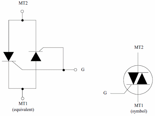
The Triac is another important device of thyristor familly. Unlike the SCR, the Triacs are bidirectional and can conduce the current in both directions. We can compare a Triac as two SCR connected in inverse parallel (anti-parallel) and placed inside a single three terminals package as shown by figure 1.
The Triac is indicated to applications where AC voltages must be controlled meaning that a large range applications in mechatronic projects powered from the AC power line.
Like the SCR the Triac can be used as a power switch controlling a large amount of alternating current from the main terminals (MT1 and MT2) from a low voltage applied to the gate.
Unlike the SCRs that need only positive voltages applied to the gate to be turned on, the Triacs can be triggered either by a positive or a negative gate signal, irrespective of the polarities of the main terminal voltages. From this fact, the device can be triggered by four modes, indicated as follows:
I+ Mode = MT2 positive and Gate current positive
I- Mode = MT2 positive and Gate current negative
III+ Mode = MT2 negative and Gate current positive
III- Mode = MT2 negative and Gate current negative
The gate sensivities in the I+ and III- modes are high and in the other modes are lower.
Common Triacs need only some miliamperes of current in the gate to be turned on and once in the conductive state high currents in the range from some amperes to more than 1,000 amperes can be controlled.
Specifications
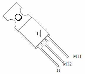
The package are the same as the used by high power transistors, SCRs and many other components. See that they are basically high power solid state switches and must be mounted in heatsinks when handling high currents. The identification of the terminals (MT1, MT2 and G) is made using the informations of the data sheet or documents of the manufacturer as it changes from type to type. A general rule is that MT1 used to be connected to the case or to the tab.
The Triacs are identificated by a part number displayed as a figure in the package, the same way the SCRs, transistors and many other solid state devices. From the part number, using a data sheet or other document from the manufacturer it is possible to find the electrical characteristics of the device. The inverse procedure is valid: from the characteristcs is possible to find a Triac by the part number, suitable to an application.
The main specifications to be observed in a Triac are:
a) Maximum voltage
It is the maximum voltage that can be applied to the Triac in the off state. They are indicated also as the Repetitive Pulse Reverse Voltage (Vrrm) or Repetitive Peak Reverse Voltage (Vrrm) and can be typically in the range between 50 and more than 1,000 volts for common types.
b) Maximum current
The maximum current that can be controlled by the device is indicated as the Continuous On-Sate Current or average On-state and can be in the range of 1 ampere and more than 100 amperes for common types.
c) Trigger current and voltage
The current that triggers on the Trac is indicated as the Gate Trigger Current and abreviated by Igt. Typically this current is in the range between some microamperes and 100 mA depending on the size of the device. The trigger voltage is also indicated as Vgt and is typically in the range between 0,8 and 1,5 volts for common types.
d) Dissipation power
When the triac conduces the voltage accross it is typically between 1,7 and 2,2 volts. This voltage times the controlled current or the load current gives the dissipation power of the device. The maximum dissipation depends on the device.
How to Use
Figure 2 shows two basic application circuit of a Triac controlling an AC motor, solenoid or a resistive load.
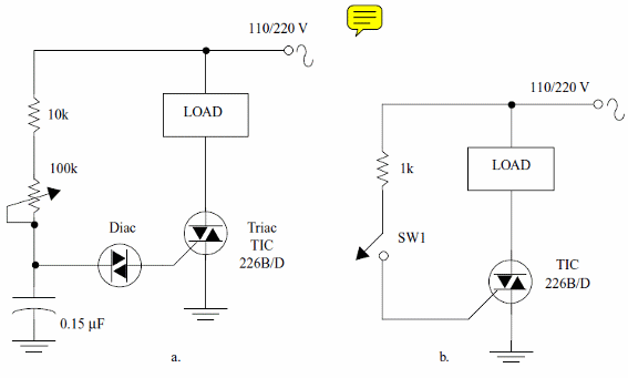
a) speed control or dimmer
b) power switch
The load is plugged in series with the Main terminal 2 (MT2) and the main terminal 1 is put to the ground.
There are four ways to trigger the Triac as described in item 10.5.
In basic applications the trigger mode in the first quadrant is the preferred as it gives more sensivity.
When turned on a voltage fall of about 2 V is noted in the device. This voltage fall determines the amount of heat produced by the device (the voltage fall x the current gives the dissipation power).
Formula - Power generated by a Triac when in full conduction state:
Pd = 2 x I
Where:
Pd is the power (W)
I is the rms current accross the triac (A)
Obs: "2" is the typical voltage fall accross a triac when in the full conduction state.
EMI
Triacs and SCRs are high speed power switches. Their turn-on and off times are very low, only few microseconds and this can cause problems of EMI or Electromagnetic Interference.
EMI or RFI (Electromagnetic Interference or Radio Frequency Interference) is the interference caused by undesirable radio signals produced by devices like the thyristors that can affect the operation of many electronic sensitive equipments. Remote control via radio as used in many mechatronic projects can be affected by intreference of Triacs and SCRs operating near them.
When a SCR or Triac is used in a circuit as power control, the high speed changes of the current in a load results in the generation of a series of harmonically related radio-frequency signals.
The magnitude of the fundamental signal is proporcional to the magnitude of the controlled current and in more part of the cases can be great enough to cause interference in AM radios and many other circuits that operate with low and medium frequency radio signals.
In special, the interference is higher when the SCR or triac control inductive loads as motors, solenoids, magnets, etc.The snap action of the triac or SCR makes the current oscillate in the circuit generating a strong electromagnetic field.
A protection circuit that minimizes the interference is shown in figure 3.
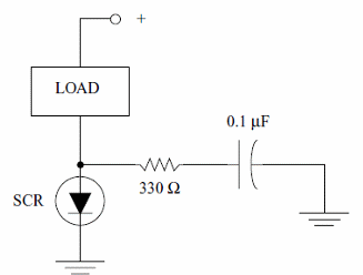
The capacitor and the resistor form a "damping" circuit reducing the current oscillation and the electromagnetic interference. The noise in an AM radio receiver, produced when a circuit using triacs or SCRs is turned on, or the small dots and points in a TV screen when the same device is turned on are examples of these interference process.
The interference can reach the radio receivers, TVs or other sensitive devices by two ways:
It can be irradiated directly into the air as a radio signal.
The undesirable signal, in general, is very weak and only cause problems if a radio or other sensitive equipment is placed near the source of interference. It is also concentrated in the low band of the radio spectrum as shown by figure 4 interferring with much more power in the LF (low frequency) and MW (medium wave) band.
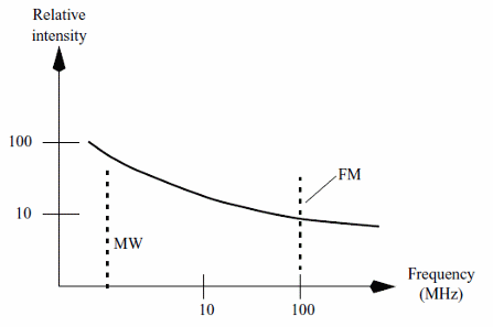
Radio receivers operating in higher frequencies as FM receivers, VHF receivers as the ones used in remote controls for garage doors, robots and cellular telephones aren't much affected by this interference not only due the less power concentrated in this band but also due their operation principles.
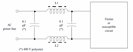
In the second case, the signal reaches the interferred equipment by the own AC power line.
To avoid the interference in this case is enough to use an L-C filter as the one shown by figure 5.
Common Triacs - Table
I,II,III
| Type | It(rms) (A) | Vdrm (V) | Igt max (mA) |
| TIC216A | 6 | 100 | 5 |
| TIC216B | 6 | 200 | 5 |
| TIC216D | 6 | 400 | 5 |
| TIC226B | 8 | 200 | 50 |
| TIC226D | 8 | 400 | 50 |
| TIC236B | 12 | 200 | 50 |
| TIC236D | 12 | 400 | 50 |
| TIC246B | 16 | 200 | 50 |
| TIC256D | 16 | 400 | 50 |