

Note: This article was originally written in Portuguese for the author's website in 2004, and later (2006) used in the book Bionics for The Evil Genius. Some changes to the original text were introduced.
Many pests such as cockroaches, slugs, and cater-pillars can he killed by the discharge produced by the high-voltage electrodes. The evil genius can add this circuit to the biologic trap or use it alone, placing it where insects are present.
The circuit is powered from the AC power line, but it is safe because the high-voltage electrodes are isolated. However, even though it is not dangerous, it can cause severe shocks if touched, so the evil genius must take care with its installation, placing it where no one has access to the electrodes. The circuit can also be used as an electric fence, keeping animals confined, as suggested by Figure.1. The uncovered wire must be isolated in this application.
Finally, we have to say that the power consumption of the circuit is very low. The evil genius can plug the circuit into the supply line without the danger of a large energy bill at the end of the month. The circuit drains less than 5 watts from the power supply line since it operates in a pulsed manner.

Bionics Applications
The great advantage of the electric killer is that it uses no chemical substances and therefore is an "eco-logical" solution for pest elimination. It can he used in many applications:
• Killing pests without the use of chemical substances.
• Capturing insects and killing them using the biologic trap.
• Making experiments with insect conditioning.
• Creating an electric fence to confine animals.
How the Circuit Works
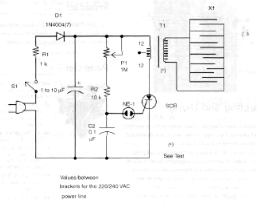
The circuit consists of a relaxation oscillator using a neon lamp to trigger a silicon-controlled rectifier (SCR).
The capacitor Cl charges through R1 and D1 until the voltage across the lamp rises enough to trigger it. At this moment, the neon lamplights up and the capacitor C2 is discharged through the gate of the SCR. The result is that the SCR conducts the dis-charge current of C1 that flows across the low-voltage winding of the transformer.
The high-voltage pulse produced at the secondary is applied to the lamp that flashes for a moment. The pulse rate can be controlled by P1, and the power of the flash depends on the capacitor C1.
The transformer can be any type that is used in power supplies, with a primary rated to 117 volts alternating current (VAC), a secondary of 9 to 12 volts, and currents that range between 250 and 600 milliamps.
Although the primary of the transformer is rated .to 4 to 12 + 12 volts (24 volts), the pulses applied to this component can reach 80 volts or more. This means that voltage induced in the primary is not 117 volts but higher with pulses rising to 400 volts or more.
In some cases, the transformer, which is not designed to support this voltage, can present some (1) leakage, with sparks between the turns of the coil. If this happens, find another transformer for the application. P-1
Depending on the components used, to compensate tolerances C2 can be changed, and values that range from 0.1 to 0.47 µF can be tested.
To operate from the 220/240 VAC power line, 1-10 change R1 to 1 kΩ, replace D1 with a 1N4007, and use the TIC106D for the SCR. It is not necessary to mount the SCR on a heatsink because it only works for short time intervals without generating large amounts of heat.
How to Build
Let's start with the complete schematic diagram for the insect killer, shown in Figure 2.
Since the circuit is very simple and no integrated circuit (IC) is used, it can be mounted using a terminal strip as a chassis. Figure 3 shows the component's placement for this mounting.
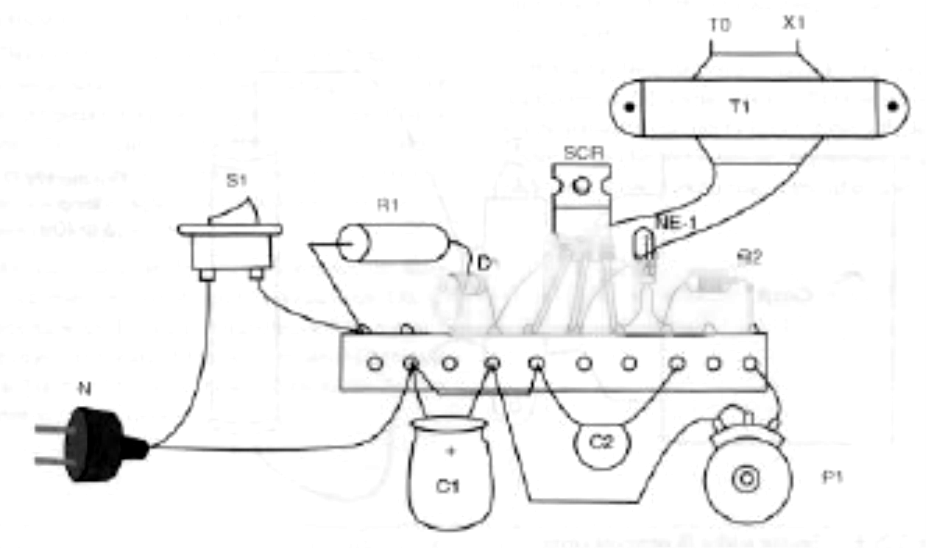
This simple way to mount is ideal for beginners who don't have the resources to make a printed circuit board (PCB). When mounting, be careful with the positions of the polarized components, such as the diodes, capacitor, and SCR.
The Trap
The trap is made using a piece of wood and some uncovered wires, as shown by Figure 4.
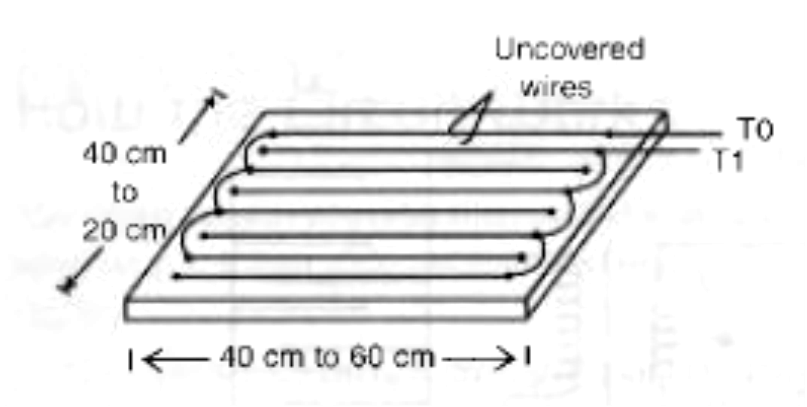
The distance between wires can vary from 0.4 to 1 centimeter, depending on the size of the insects to be killed. This distance is determined .by the fact that the insect must touch two wires at the same time to receive the electric discharge. The wires to the circuit must be isolated, and the maximum length is 3 meters.
Testing and Using
Testing is easy. Plug the circuit into the AC power line and connect the output of the circuit to a fluorescent lamp, as shown in Figure 5.

Adjusting P1, the lamp will flash, indicating the generation of high-voltage pulses. If you are a courageous evil genius, plug the trap into the circuit and verify the discharge, touching your fingers to the wires. Make adjustments until you are able to produce the brightest flashes in the fluorescent lamp.
Now you can use the insect killer. Use some substance (sugar for cockroaches, for instance) and place the killer in a place where you judge the insects to be.
Important
The circuit doesn't have problems with shorts. Even if an insect dies making a bridge between wires, this won't cause any problems for the circuit.
Parts List
Required Parts
SCR: TIC106B (117 VAC power line) or TIC106D (220/240)
D1: 1N4004 (117 VAC) or 1N4007 (220/240 VAC) silicon rectifier diode
NE-1: NE-2H or equivalent neon lamp
R1: -470 Ω x 10 W (117 VAC) or 1Ω x 10 W (220/240 VAC) wire-wound resistor
R2: 10 kΩ x 1/8 W resistor, brown, black, orange
R3: 47 kΩ x 1/8 W resistor, yellow, violet, orange
P1: 1 MΩ lin or log potentiometer
C1: 4.7 to 22 µF x 200 V (117 VAC) or 400 V (220/240 V) electrolytic capacitor
C2: 0.1 µF x 100 V or more polyester capacitor
T1; Transformer (see text)
X1: Electrodes (see text)
Other: PCB or terminal strip, power cord, plastic box, wires, etc.
Additional Circuits and Ideas
High voltages can he generated by many different electronic configurations. Some of them are discussed in the next section.
Very High - Voltage Killer
Very high voltages can be generated using a horizontal transformer or a flyback transformer, such as the one shown in Figure 6 in the basic circuit.
This transformer will replace T1 in the basic circuit and can generate voltage pulses reaching up to 10,000 volts, certainly enough to kill any insect, regardless of its size! For this purpose, the evil genius must make the primary of the transformer, placing 20 to 30 turns of common wire at the core of the transformer, as shown in the figure.
Another change in the project is to place the wires with a certain amount of space between them. Distances between 0.5 and 1 centimeters will be necessary to prevent sparks from being produced between them. Figure 3.15.7 shows how to connect the flyback output to the electrodes.

High voltages can also be obtained from spark coils, such as the ones used in cars or motorcycles. In this case, however, the evil genius must take care when mounting and using the circuit, because the primary and secondary are not isolated. This means that the wires in the trap will not be isolated from the power supply line, and any accidental touch can cause a severe shock.
Using a Laser
A very interesting idea to be developed is shown in Figure 8. The basic idea is a scanner that detects the passing of a fly by both an image sensor or another way.
When the fly is detected, a laser is triggered, striking the insect. Of course, simple LED lasers would not be powerful enough to knock down a fly, so helium-neon (Helve) lasers or even more powerful ones must be used (with much care, of course).


