Note: This article was originally written in Portuguese for the author's website in 2004, and later (2006) used in the book Bionics for The Evil Genius. Some changes to the original text were introduced.
Of course, detecting when someone is lying is not so simple. Interpreting the changes in skin resistance and preparing the subject for an interrogation require special skills from a professional who works with a lie detector.
Thus, the project described here is not infallible and serves as an object of curiosity to demonstrate how such a machine operates. The evil genius can use it with his or her friends more for fun than as a serious device that can detect a lie under any condition. The changes in skin resistance can also be used as a feedback circuit. Real lie detectors are not easy to use. The specialists are trained not only to observe the signal indicators but also to observe how the person reacts and small details not seen by untrained persons. These specialists study for years to become successful operators of lie detectors.
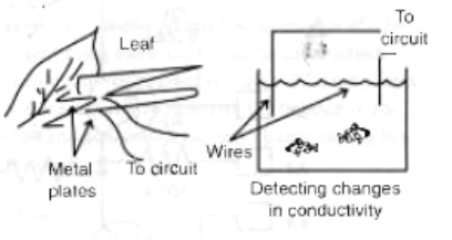
Finally, the project can be used to detect changes in the external resistance of other living beings such as plants or fish in an aquarium, or in areas where changes are related to biological activities. Coupling an electronic device with a living being is what bionics is all about, as this hook will convey.
Projects in Bionics
Mounting the lie detector, the reader can perform the following experiments and applications:
• Show how an experimental lie detector functions.
• Detect changes in a living being's body resistance under certain conditions, performing experiments with stress circadian rhythms, and so on.
• Use the circuit for visual feedback...
• Detect changes in environments where living beings are present.
• Detect biological activity in some experiments. (Any biological activity produces electric signals. Those signals can be observed using this circuit as a biologic amplifier.)
How the Circuit Works
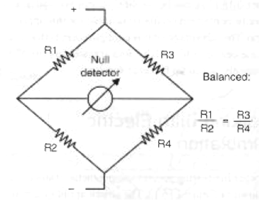
The basic circuit consists of a Wheatstone Bridge where one of the arms measures the resistance of the subject under interrogation. The null or zero indicator, which appears when the bridge is balanced, is a common analog galvanometer. Figure 1 shows the basic circuit of a Wheatstone Bridge.
Simply place the electrodes in the hands or on any point of the subject's skin and then balance the bridge, using a potentiometer for this task. Any change in the resistance of the subject will be sensed by the bridge, which goes out of balance, and is indicated by the galvanometer.
The circuit is powered from four AA cells or a 9-volt battery. Because the current drain is very low, these supplies will have an extended life.
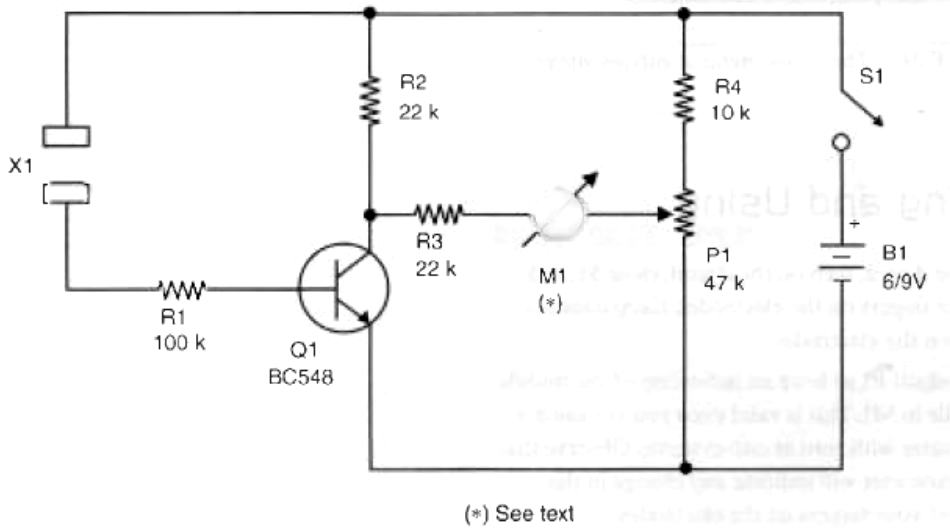
It is also important to make sure that the current flowing through the electrodes is extremely low and does not cause any sensation for the subject or pose any danger to cause a shock. The presence of the transistor is just to act as an amplifier for the very low currents that flow across the skin of the subject.
This basic circuit can be changed and many upgrades can be added to improve its performance. Making these changes will be covered in the "Additional Circuits and Ideas" section.
Building the Lie Detector
Figure.2 shows the complete diagram of the lie detector in its basic version using an analog galvanometer as a null detector.
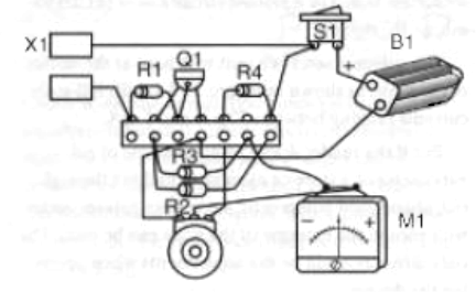
Since few components are used, the ideal for the evil genius who is learning about electronics is to use a terminal strip as a chassis, as shown in Figure 3. Of course, the more experienced evil genius can use a solderless board or a printed circuit board (PCB) to mount the circuit.
The galvanometer is a unit with zero at the center of the scale as shown in Figure 4, with full-scale currents ranging between 50 MA and 1 mA.
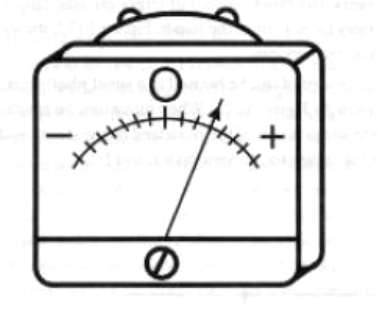
But if the reader doesn't find this type of galvanometer at a store or even after looking through old, abandoned equipment, a common galvanometer with zero in the extreme of the scale can be used. The only difference will he the adjustments when operating the device.
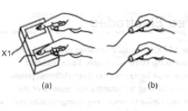
The electrodes can be constructed in a couple of different ways. One of them is to use two small metallic plates upon which the subject can place his or her fingers. The other consists of larger metallic electrodes to be kept in the hands. Figure 5 shows these two options.
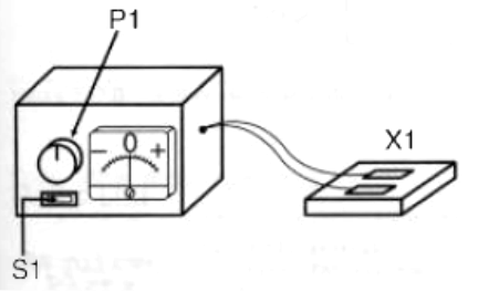
The circuit can be housed in a small plastic box, as shown by Figure 6. When mounting, be careful with the position of the polarized components, such as the transistor, galvanometer, and B1.
Testing and Using
To test the device, turn on the circuit, close S1, and place your fingers on the electrodes. Keep constant pressure on the electrodes. N
Then adjust P1 to have an indication of the middle of the scale in M1. This is valid even you are using a galvanometer with zero at one extreme. Observe that the galvanometer will indicate any change in the pressure of your fingers on the electrodes.
In an interrogation, the subject would need to keep constant pressure on the electrodes and not let the indicator move. If any movement occurs, it is because the person is lying. During a test, you would 164 only have to ask the questions and keep an eye on the indicator.
When performing experiments with plants or other living beings, the procedures are the same: Start from the point where the bridge is balanced. Any change in the balance will he indicated by the galvanometer.
Parts List
Required Parts
Q1: BC548 general-purpose NPN silicon transistor
M1: Galvanometer (see text)
X1: Electrodes (see text)
R1: 100 kΩ x 1/8 W resistor, brown, black, yellow
R2, R3: 22 kΩ x 1/8 w resistors, red, red, orange
R4: 10 kΩ x 1/8 W resistor, brown, black, orange
P1: -47 kΩ potentiometer, lin or log
S1: On/off switch
B1: 6 or 9 V AA cells or battery
Other: Terminal strip or PCB, plastic box, cell holder or battery connector, wires, solder, etc.
Additional Circuits and Ideas
Many improvements can he used to increase the performance of this circuit or change it Some of them are described in this section.
Darlington Configuration
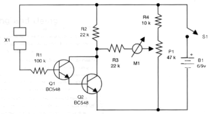
The transistor used in the basic project is a common bipolar type with gains that range from 125 to 800. The sensitivity of the circuit can be increased with the use of two transistors wired in a Darlington configuration, as shown in.7.
When wired as a Darlington pair, the gain of the stage will be the product of the individual transistor’s gains. For instance, if each transistor has a gain of 400, the total gain of the stage will be 160,000 (400 X 400). This circuit can detect very small changes in skin resistance due to the high gain of the Darlington stage.
The parts list is the same, but the transistor is replaced by two BC548s.
Three Electrodes
Figure 8 shows an interesting version of a lie detector using three electrodes. Since constant pressure must be exerted on three different points, it is more difficult to maintain the balance of the circuit and easier to detect any change during the interrogation.
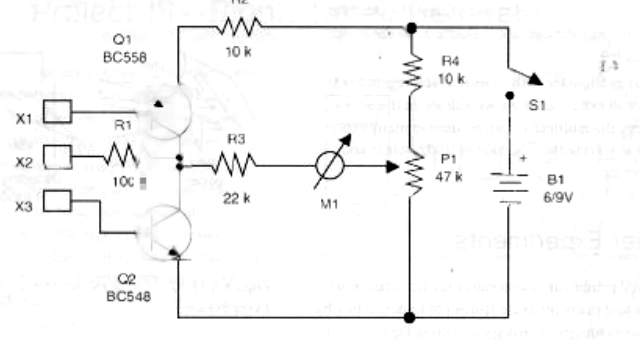
Parts List
Required Parts
Q1: BC558 general-purpose PNP silicon transistor
Q2: BC548 general-purpose NPN silicon transistor
M1: Galvanometer (see basic project)
X1, X2, X3: Electrodes (see basic project)
R1: 100 kΩ x 1/8 W resistor, brown, black, yellow
R2, R4: 10 kΩ x 1/8 W resistor, brown, black, orange
R3: 22 kΩ x 1/8 W resistor, red, red, orange
P1: 47 kΩ potentiometer, lin or log
M1: Galvanometer, as in the basic project
S1: On/off switch
B1: 6 or 9 V cells or battery
Other: Terminal strip PCB, cell holder or battery connector, plastic box, wires, etc.
Using a Multimeter
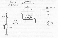
Digital multimeters are not suitable for this application because the numbers in the display change so fast that we can't see what they are saying. In this project, what is important is not a fixed number but the ability to detect changes. Thus, an analog multimeter is the best replacement for the galvanometer and is wired as shown in Figure 9.
The scale of the multimeter is the lowest for currents (normally some micro amps) and the measurements for adjustments are the same as in the basic project.
Any multimeter with sensitivity starting at 1,000 ohms/volt can be used. As we will see in the next projects, the multimeter can be used in many experiments involving the interface of living beings and electronics.
Other Experiments
The evil genius can also connect the lie detector to plants and many other creatures not to detect lies, but to detect changes in biological activities. Figure 10 shows how to connect electrodes to a couple different specimens.
The important point to observe in the connections is that the circuit detects changes in the resistance the same way that the bio-amplifier does.
