

Note: This article was originally written in Portuguese for the author's website in 2004, and later (2006) used in the book Bionics for The Evil Genius. Some changes to the original text were introduced.
In previous projects, we worked with oscillators that generated sounds, ultrasounds, and electric and magnetic fields. Here we are going to give a circuit more capabilities that can be used in experiments and applications interacting with living beings.
Experiments and Applications in Bionics
The curious evil genius can use the oscillator described here to see how many living beings react to medium- and high-frequency fields. He or she can also use it on insects or plants to see how they change their habits or growth.
The Circuit
After having described other circuits in this book, this additional configuration is dedicated to the generation of high frequencies that range from 100 kHz to 20 MHz. The circuit is a Hartley oscillator, generating up to S watts of high-frequency signals that range from 100 kHz to 20 MHz, depending on the coil (L1).
In a Hartley oscillator. L1 and CV determine the frequency of the signals generated by the circuit. C2 and R I form the feedback network that keeps the oscillator running.
The signal generated by the circuit is picked up from a second coil in the same form of L1. This coil acts as the secondary of a transformer where Ll is the primary.
The power supply comes from a battery or a sup-ply with output voltages ranging from 6 to 12 volts. The maximum drained current is around 800 milliamps and depends on the tolerance of the components and the transistor gain.
How to Build
Figure 1 shows the diagram for the medium/ high-frequency oscillator. The circuit can be mounted using a small printed-circuit board (PCB), but the evil genius without the resources to make a PCB can use other techniques, such as a solderless board or even a terminal strip.
The coils (L1 and L2) depend on the frequency. Their characteristics are given in Table.1.
Table 1 - Coil characteristics
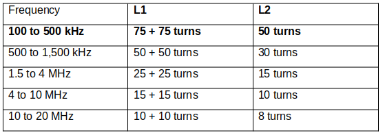
The coils are made with 26 to 30 AWG wire on a ferrite rod 15 to 20 centimeters long and with a diameter of 0.8 to 1 centimeters. Also, L2 is placed on L1.
CV is a common variable capacitor, such as ones found in old AM radios. The maximum capacitance must range between 200 and 400 pE. The transistor is mounted on a heatsink and a power supply suitable for this oscillator is given in Figure 3.


Testing and Using
Testing is very easy. Simply place a radio receiver that can tune the frequency of the oscillator near the circuit. Any short-wave receiver tuning from the long wave (LW) to the short wave (SW) bands, can be used in the test according to the coil used.
Place the oscillator near the receiver and turn on S1.Tuning CV the signal produced by the oscillator will be heard like a wind in the loudspeaker of the receiver. The range will depend on the sensitivity of the receiver but will not be more than some meters.
Since the circuit drains a high current, do not use AA cells. Use four C or D cells. For long-term experiments, use the power supply suggested in Figure 3.

Parts List
Required Parts
Q1: BD135 medium-power NPN silicon transistor
L1/L2: Coils (see text)
R1: 1 kΩ x 1/2 W resistor, brown, black, red
C1: 0.01 µF ceramic capacitor
C2: 0.1 µF ceramic capacitor
CV: Variable capacitor (see text)
Other: Power supply or batteries, ferrite rod, wires, solder, etc.
Experiments and Applications in Bionics
Some experiments using oscillators were suggested in previous projects, but here are a few more.
Experiments with Plants and Insects
Figure 4 shows how to apply the signals generated by this oscillator to specimens via radiation.

Direct Application of the Signals
Direct application of the signals can be made by connecting the electrodes wired to the output of the circuit, as shown by Figure 5.
This circuit includes an amplitude control that regulates the amount of power sent to the specimens. The power in the circuit's output can reach a certain number of watts, which would be enough to kill small creatures and plants. Be sure to not apply the signal to humans.


