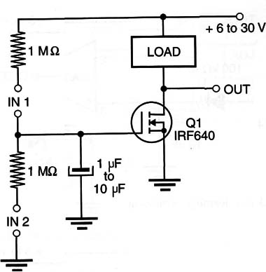
Any short pulse applied to INl pumps a small charge into capacitor C, increasing the output voltage. The pulses applied to [NZ drain some charge from the capacitor, decreasing the output voltage.
The output voltage can be used as reference in a block comparator or other circuit that will change its performance according to the number of pulses that have been applied to the inputs. We can say that, depending on the pulses applied to the inputs, the circuit can be conditioned or can learn and generate an appropriate response.
The number of pulses required to teach this circuit depends on the value of the capacitor. This component can assume values in the range between 1 and 10 µF. Polyester capacitors are recommended, because their charge retention time is longer than that of electrolytic capacitors. It is important to remember that this circuit is not linear, and the output voltage jumps to near zero when the power FET reaches the saturation point.
The circuit can directly drive high-power loads. Replacing the load with an 1 k ohm resistor, the output voltage can be used as a reference for comparators.


