

I have adopted this project in my own mechatronics course, designating it as the second practical activity of the year. Students aged 11 to 14 are required to construct a race car in two versions (fan propeller or gears) and enter their finished products in a race.
The car, built with such miscellaneous parts as cards and parts of toys is basically light controlled.
A flashlight is used to control the small DC motor that’s used as an engine. In the race, the cars are distributed in teams of six to eight and aligned at a starting point.
They have to cover a distance from 1,0 to 20 meters in a straight path and cross the finish line.
Figures 1 and 2 show my pupils with their cars at Colegio Mater Amabilis in Guarulhos, São Paulo, Brazil. Since being published in Brazilian magazines, this project has been adopted by schools around the world.
")
")
The simple competition challenges students to build the best car (the lightest and fastest). However, the project can also serve an educational purpose.
Pupils can learn much about physics, technology, and other sciences while working with others to build a race car.
Objectives
There are many objectives when building a race car:
- Learn how to build simple projects by using a terminal strip
- Learn how photocells or photosensors (light-dependent resistors -LDRs) function
- Design a propulsion system that uses gears or a fan
- Learn about friction and how it can be reduced
- Learn how a transistor works as a switch
The Project
As shown in Figures 3 and 4, we can build the race car in two different versions: by using a fan as a propeller or by using gears that transfer power from the motor to the wheels.


The choice depends on the resources at hand.
In the fan version, the fan can be constructed using a common compact disc (CD), out and bent with the aid of some heat.
Although this is the simplest method of construction, the CD is very delicate and many fans break during the competition or even while being cut and bent to form the fan. It is recommended to have many fans ready to serve as possible replacements during the competition.
Another method is the use of plastic or wooden fans, such as those used in aircraft models. It is up to the reader to find the fan that best suits the project.
Certainly, the evil genius will be able to identify the best fan needed to win a competition. Studying characteristics such as the ratio between area and motor speed, diameter, and weight, the evil genius can ultimately identify the fan that will propel his or her car ahead of the competition.
Usually, the gear version is more efficient. However, although the race car may be faster, the issue remains as to how to find the appropriate gears. We suggest using parts of toys or electrical or electronic appliances. These parts should be an accessible gear source for most readers.
The project can be divided into two parts:
The electronic circuit
The mechanical part (the vehicle)
As a general rule, inexperienced builders should allot at least 4 hours of work for each part of the project. To make it easier for my students, I prepare kits that include the electronic parts, motors, sensors, and transistors. This is particularly important if you are moderating a competition; it ensures that the competition will not be determined by the materials used, but rather by the skill of the designers.
Rules are provided determining the dimensions of the cars, the power supply, and other items that could potentially make some difference in the race. The evil genius can suggest a competition with his or her neighbors or at his or her school.
How it Works – The Electronic Circuit
The basic electronic circuit is the same for the two versions, so the description of its operation principles is valid for both.
The sensor is an LDR (cadmium sulfur-CdS) cell or photoresistor), controlling the base current of a transistor.
A Darlington transistor, or high-gain transistor, is used as a switch that controls the current flowing across the motor.
When the LDR receives light, its electric resistance falls, switching the transistor. At this moment, it passes from the off state to the on state, and the current flows to power the small DC motor.
See that the transistor acts only as a switch and does not amplify the light.
This is important when choosing a light source to be used as a remote control.
This means that, when activated by the appropriated light level, the transistor becomes saturated and no additional power can be used to drive the motor. A saturation curve is shown in Figure 5.

It is important to make clear that it is not the power of the flashlight that excites the LDR and determines the final speed of the car but rather many other mechanical factors.
The flashlight is used only to turn on and off the circuit, not to power it. It serves as the remote control, not the power source.
With the aim of receiving the light only from the flashlight, the LDR is mounted inside a small card tube. Some type of cover should be used to avoid the effects of ambient light prior to the start of the race.
One idea is to allow the ambient light to act on the LDR. Therefore, when the race begins, the competitor need only remove the cover from the sensor, allowing the ambient light to switch on the motor.
The power supply for the car is formed by four AA cells, and other cell sizes are not recommended.
Large cells, such as C or D cells, do not add power in the same proportion to the rise in the weight they cause, so the speed tends to decrease.
Furthermore, the excess of current can overheat the transistor and possibly burn it out. We recommend the use of new alkaline cells on the day of the race.
Attaching a smal heatsink to the transistor may be necessary in some cases.
How it Works - Mechanical Part
The chassis is the same for the two versions with small differences only in the propulsion system.
Cardboard, plastic, or even light wood can be used to form the chassis, the place where the electronic circuit, motor, and propeller are mounted. The builder is free to make changes in the original project, as shown in previous figures.
Three-wheel versions are accepted. The builder must take care with the alignment of the wheels to be sure that the vehicle will move in a straight line.
Remember that the only control you have is in switching the motor on and off.
In the fan-propelled version, the motor is placed on a small platform built with common pieces. An empty inkjet cartridge is used to support the motor in Figure 1, for instance.
Building the Race Car
Now we can start with the construction of the race car, which is divided in two parts. In the first part, we will describe how to assemble the electronic circuit.
In the second part, we will see how to mount the mechanic part of the car.
Electronic Circuit
Figure 6 shows the complete circuit of the light- operated remote control used in this version of the race car. A second version will be described in ART034E.

This circuit can be mounted using a small terminal strip as a chassis, as shown in Figure 7.

When assembling the circuit you must observe the following:
The position of the transistor.
The polarity of the power supply (cell’s holder) and the motor. If the motor rotates in a direction that moves the car backward, invert the wires.
Do not let any of the components’ terminals touch each other. This can cause a shortage and risk melting.
Q1 is any Darlington transistor rated to 2 amps or more. If the transistor tends to overheat, attach a small piece of metal to act as a heatsink, as shown in Figure 8.

Remember: The heatsink means more weight added to the car and might reduce its final speed.
The next photos show details of the contruction of the race car.
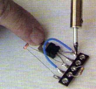
a) Soldering the components
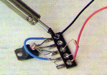
b) Soldering the wores
c) Connecting the motor
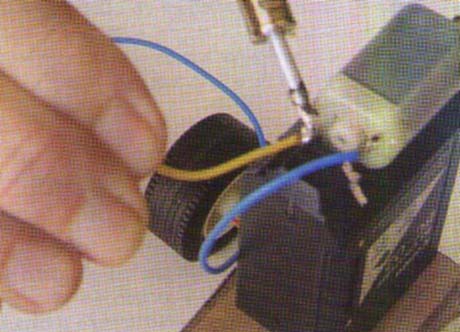
d) Protecting the LDR with an opaque tube
Any common LDR can be used in this project. Small round types are ideal because they can be easily placed inside the card tube and improve directional control.
The LDR must be placed inside a opaque tube to receive the ligh only from one direction: the lantern.
Mechatronic Race Car Electronic Circuit
Q1 TIP/122 or equivalent, Darlington NPN transistor
LDR -Photoresistor or LDR (CdS cell)
R1 - 1M ohm x 1/8-watt resistor (brown, black, red)
M1 - 6-volt small DC motor
B1 – 6 volts – 4 AA cells
Miscelaneous: Cell holder, wires, terminal strip, etc.
Mechatronic Car – Using a Fan
Common materials such as cardboard, plastic files, light wood, or metal (aluminum, zinc, etc.) can be used to build the race car’s chassis. Figure 9 shows the basic dimensions of the chassis when using a fan as a propeller.

The dimensions given in Figure 13 represent the average.
The builder can change them according to the size of wheels he or she intends to use and according to other design factors. It is important that the organizers of the race limit the dimensions to avoid aberrations in the competition.
Such wheels can be found in toys and can be installed on the race car, as shown in Figure 10.

Small plastic drinking straws are often used as axles to complete this task.
It is important that the straws be long enough to position the wheels firmly, as the car must run in a straight line. The motor with the fan can be installed at the top of an empty cartridge of an inkjet printer.
Use glue or another method to fasten it in position.
Figure 11 shows how the fan is built from a CD. Cut it and bend the blades using the heat of a candle or another heat source. Be careful not to burn or break the blades.

The fan constructed with a CD is very delicate. breaking easily at any impact. Have several units available to replace them during a race or test.
Many fans can break during a competition.
The fan is glued to a small plastic wheel taken from a toy. Be sure that the wheel is centralized. Otherwise, the fan will vibrate when running, either breaking off or taking the car off its straight line path.
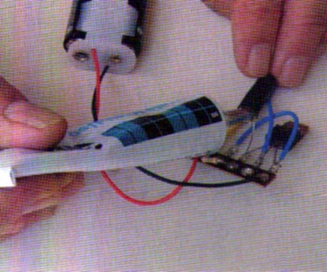
The batteries and the electronic circuit are placed in the chassis.
Perform tests to see if the vehicle runs forward when activated. If not, invert the wires to the motor.
Mechatronic Car-Using Gears
The chassis is the same as the one used in the fan version. The basic difference is in the way the wheels are fixed, and the gears transfer the power of the motor to the wheels.
Figure 12 shows the chassis and the basic dimensions. See the cut in the part where the gears are installed.

First, prepare the chassis and find two pairs of wheels with the axis as shown in Figure 13. In one axis, place a plastic gear between 2 and 4 centimeters.

The gear must be smaller than the diameter of the wheel in order to avoid contact with the ground.
In the motor’s spindle, insert a small gear as shown in figure 14. The two gears can be found in toys and electronic appliances. It is important to test combinations of gears that result in the best performance for the car.
The performance changes according to the size of the wheels and the weight of the car.
The wheels with an axis are placed in the chassis as shown in Figure 14.

See that the hole in the chassis allows the gear to adjust the motor without any contact with adjacent parts.
Be sure that the wheels are aligned to permit the car to run in a straight line and reach the highest speed possible.
The next step in mounting is to place the motor. Use rubber bands as shown in Figure 15.

The motor can be placed in contact with the gears in other ways, but the advantage of using the rubber bands is that they can act as dampers to absorb the impact of obstacles or irregularities in the lane or in the alignment of gears.
Test the transmission system that powers the circuit to verify that all the power is transmitted to the wheels. If the wheels run backward instead of forward, invert the wires to the motor.
Now we can install the electronic circuit and the batteries as shown in Figure 16.

Protect the sensor from light when installing the circuit. A small piece of plastic or cardboard can be used. A pen cover can be used to execute this task.
After wiring the circuit power, verify that the car moves in the correct direction. If it runs backward, invert the wires to the motor.
Testing the Car
1. Cover the LDR and insert the cells in the cell holder. Take care to avoid inverting any of the cells.
2. Align the car with others in the lane and remove the cover of the LDR. If the ambient light is sufficient, the motor will start and propel the car forward. If not, use a flashlight to illuminate the LDR.
3. If the motor does not run, check the contacts of the cells in the holder.
4. If the motor runs backward, invert the wires.
If the circuit triggers even when the LDR is covered reduce the value of R1 to 470 k or 220 k.
Now the car is ready for the race. Start your engines and go!
The Race
Although the reader is free to create his or her own rules for a competition, I am experienced in facilitating this type of race. I have been organizing the event for the past 8 years in the college where I teach mechatronics.
Figure 17 shows one of these competitions

I have adopted the following rules:
The pupils form teams of two or four members building one or two cars. In the case of two cars, as in real cars, one is the main car and the other acts as the reserve.
The cars must have the same motors and dimensions in the following range: length, 15 to 25 cm; width, 4 to 6 cm.
In the case of a school project, two evalua tions are made: one for construction and one for race performance.
If more than eight cars will participate, they can be divided into groups of two or three for the final race.
The racer (student) can’t touch the vehicle. A loss of points can be used to punish for such an infraction.
The points attributed to the cars can be as follows:
Winner: 4 points
Second place: 3 points
Third place: 2 points
Cars that cross the final line: 1 point
Cars that complete half of the course: 0.5 point
Other conditions: combined by the organizer
When using a flashlight as a remote control, the flashlight must be placed at least 30 cm from the LDR.
Cars who crash or take other cars out of the competition due to changes in direction will be punished or disqualified.


