

Obs. This article is obtained gathering several projects the autor published in books and Brazilian magazines. They were translated into English and then included in the book Mechatronics for the Evil Genius – TAB 2006, published in USA.
The name of the alternative source of energy represented by the wind is eolic from the Greek word Eos, meaning wind. Eolic generators are devices or transducers that convert eolic energy, or the energy of the wind, into electricity.
This article describes a simple eolic generator with an output great enough to power small electronic devices. This section also describes variations on the project for increasing the generator’s power and for building other devices that can be used in heavy applications as alternative energy sources.
Our article will allow readers to save costs related to the use of traditional electrical energy sourced through the local energy distributor and to use some of the free power delivered by Mother Nature.
Our basic eolic project is very simple and will produce only enough energy to show you that it is possible to make the conversion. A variety of experimental circuits are suggested that can be powered by your eolic project.
You will learn a good deal about eolic energy and even create a lighting system, a simple radio, a light-emitting diode (LED), and other simple devices that can be powered by your alternative energy source.
Objetives
Show how the power of the wind can be converted into electrical energy.
Use a small DC motor as a dynamo to power small electronic appliances.
Learn how a dynamo works.
Have an idea about the amount of wind power that is possible to convert into electrical energy.
Know how to design a powerful eolic generator.
Basic Project
Figure 1 shows that a small eolic generator can be built using any DC motor.

Applying enough wind to move to the fan, the power released by the wind Via the fan is converted into electrical energy. The amount of energy delivered by the system depends on several factors such as the following:
The size of the fan (or the amount of wind that can be collected)
The size, or the power, of the motor used as generator
The amount of wind or speed of the wind in the place where the eolic generator will operate
The efficiency of the system when transferring the fan movement to the motor
By combining these four factors, it is possible to predict the ideal size of the fan for a particular DC motor (generator), to know the amount of energy that will be released, and to know what is ideal for the application the reader has in mind.
Small DC motors don’t require more than a fraction of a milliwatt of electrical power.
However, this small amount is enough to power a small experimental radio, light an LED or small lamp, or charge a battery.
The ability to charge a battery can be especially important: You can charge the battery of a lantern, cellular phone, radio, cellular or other appliance in order to use them when you need them.
If you find yourself in a place where other energy sources are not available, the solution of an eolic generator should be considered.
Important information is given later in this project for the reader who wants more than just the few milliwatts of power generated by the basic project.
How it Works
As you learned in other projects in this section on galvanometers and electromagnets, when a current passes across a wire, a magnetic field is created.
This phenomenon can be used in several devices such as motors, electromagnets, solenoids, and relays.
In a DC motor, for instance, the magnetic field created by a current can be transformed into real movement when it interacts with the field of magnets (or the field created by other electromagnets).
The important observation regarding magnetic fields that are produced by an electric current is that an inverse effect is noted: When a magnetic field acts on a wire, a current is induced. Figure 2 shows that if a magnet moves near a wire, a current is induced, flowing across an external circuit.

Observe that the lines of the magnetic field must cut the wire to cause the induction. If the magnet moves parallel to the wire, no induction occurs.
However, the featured fact in this phenomenon is that the power released to move the magnet is converted to electrical power, released by a current across the external circuit.
To increase the amount of power induced in this process, a coil can be used instead of a single wire.
When the magnet passes near the coil, many turns are cut at the same time and therefore the induction process is magnified, creating a greater amount of electrical power.
This is exactly the principle behind the operation of a dynamo or alternator. A coil turns inside a magnetic field created by magnets. When crossing the magnetic lines of the field, electrical energy is generated. Figure 3 shows the structure of a dynamo.

An important fact to keep in mind about dynamos is that they don’t create energy; they only transform mechanical energy into electrical energy. This means that the amount of electrical energy produced by a dynamo is always less than the amount of mechanical energy supplied to it, because no generator can convert 100 percent of the power.
A DC Motor as a Dynamo
In a small DC motor, the electrical current flowing across the coils creates a magnetic field that interacts with the field of a permanent magnet, producing the power that moves the rotor.
This architecture can operate in the inverse mode as well. When forcing the rotor to turn, the coils will move, cutting the magnetic lines of the magnetic field created by the magnets.
This means that electrical energy is induced in the coils. This energy can be conducted to an external circuit, as shown in Figure 4.

Small DC motors rated at voltages from 3 to 12 volts can conduct currents up to 200 mA according to their size.
Of course the amount of energy produced by a motor, designed as a dynamo, depends on several factors:
The speed of the motor
The size of the motor
The amount of mechanical power being sourced
The idea behind this project is to use wind as an alternative energy source, but the reader should also consider exploring energy from other sources. This could entail water flowing (a creek or waterfall) or a mechanical system (mechatronic) controlled by your own muscular power or some animal, as is suggested by Figure 5.

How to Build
Figure 6 shows the complete circuit for the eolic generator.

The capacitor is used as an energy reservoir, keeping the output voltage almost constant, even when the speed or power of the wind changes. The diode does not allow the current to return to discharge the motor across the coils. The larger the capacitor is, the more energy it can store, and the lower the voltage changes in the output will be when the speed of the wind varies.
The fan can be coupled to the motor directly. If gears or other mechanical systems are used, be sure that they don’t cause energy losses, thus reducing the output of the generator.
Figure 7 shows a system using a small plastic fan being used in eolic demonstrations as the low power energy source (i.e., as a replacement for the wind).

When mounting, it is necessary to determine the direction of the rotation relative to the diode. Rotation in one direction will cause the pole in the diode to be positive.
And if the rotation is inverted, the pole in the diode will be negative, and no current will flow to the circuit.
Eolic Generator
M1 - Small DC motor (3 to 12 volts)
D1 - 1N4002 or equivalent silicon rectifier diode
C1 - 1,000 µF to 4,700 µF X 6 volts or more electrolytic capacitor
Fan, wires, terminal strip, solder, etc.
Testing and Using
It is important to know the amount of energy produced by your eolic generator. If you have a multimeter, it is easy to test the generator. Adjust the multimeter to read DC volts on a low-voltage scale and connect it to the output of the generator, as shown in Figure 8.

The figure shows a low-cost analog multimeter, but you can make the same test using a digital multimeter. By turning the blades of the fan from any wind source (a small household electric fan, for instance), the generated power will move the multimeter’s needle, indicating the voltage in the output.
If no voltage is produced, invert the wires to the motor (the diode is reversed biased).
If you do not have a multimeter, you can use the circuit LED and lamp shown in the following paragraphs on powering circuits.
Powering Circuits
The amount of power generated by the eolic generator varies across a large range of values. Therefore, don’t expect to power high-power devices using your prototype. With that in mind, some suggestions on low-power projects that can be powered by your project are also included.
LEDs and Lamps
Small LEDs and low-voltage lamps (such as the ones used in a flashlight) don’t need large amounts of power to operate. Figure 9 shows how you can power those devices using an eolic generator.

The lamp is a low-power 6 V X 20 to 50 mA type. More than one LED can be powered from your generator.
As you will observe, the amount of light will depend on the speed of the fan.
Powering Lamps LEDS
L1 - 6 V X 50 mA incandescent small lamp
LED1 - Any LED (red, green, yellow)
R1 - 1 k ohm X 1/8-watt resistor (brown, black, red)
Wires, solder, terminal strip, etc.
Battery Charger
The eolic generator can charge nickel cadmium (NiCAD) cells using the circuit shown in Figure 10.

This is the simplest version of a battery charger. The maximum number of batteries under charge depends on the voltage produced by your generator.
To determine how many batteries you can charge at one time, it is necessary to measure the output voltage of your generator. A multimeter shown in the testing and using section can be used for this task.
For each 1.5 to 2 volts of voltage, you can charge one 1.2-volt NiCAD cell, as shown in Figure 11.

For instance, if your generator produces a 6-volt output, you can Charge four AA, AAA, D, or C cells at one time. The time to charge the batteries also depends on the current crossing the circuit. Use the multimeter to measure the current.
If your generator is powerful enough to produce more than 9 volts, and the current rises up to 500 mA, you can add the constant current source as was describe in other article in this section.
A constant current source will help you create a better battery charger.
Experimental Radio
Another simple circuit that can be powered from your eolic generator or even from less powerful alternative energy sources is the experimental radio shown in Figure 12.

Even chemical and solar cells with voltages in the range of 1.0 to 6.0 volts can be used to power this very low-current circuit. In fact, the current drained by the circuit from a 2-Volt source is less than 100 ,uA.
Figure 13 shows how the experimenter can build this radio using a terminal strip as a chassis.

Of course, the radio can be mounted using other techniques, such as using a printed circuit board (PCB) or solderless board.
Only one transistor is used as a signal amplifier in this radio. Therefore, the radio is not overly sensitive and needs a long antenna to pick up local stations.
The antenna can be made with a piece of long Wire, 5 to 20 meters long. The ground connection is important and can be made through any metallic body in contact with the earth or even with your body. Even holding the ground alligator clip between your fingers will give good results. Remember to never use the radio during a thunderstorm!
L1 is formed by using 40 to 60 turns of 28 AWG enameled wire in a ferrite core with a length of 15 to 20 centimeters and a diameter of 1 to 1.5 centimeters.
The variable capacitor can be taken from any old AM radio.
The transducer is made from a high-impedance piezoelectric phone such as the ones found in telephones, buzzers, and other appliances. Take care to not use a low-impedance type as it won’t function in this project.
Experimental Radio
Q1 - BC548 or any negative-positive-negative (NPN) general-purpose transistor
D1 - 1N34 or 1N60 or any germanium diode
R1 - 4.7 M ohm X 1/8-watt resistor (yellow, violet, green)
R2 - 47 k ohm - 1/8-watt resistor (yellow, violet, orange)
C1 - 0.047 µF (47 nF) ceramic or polyester capacitor
C2 - 0.1 µF (100 nF) ceramic or polyester capacitor
X1 - Piezoelectric transducer
L1 - Antenna coil (see text)
CV - Variable capacitor (see text)
A, G - Antenna and ground connections
Ferrite core, terminal strip, antenna, alligator clip, wires, solder, knob for the variable capacitor, etc.
Automatic Light
The circuit shown in Figure 14 activates a small lamp at dusk and turns it off when the sun comes up.

The wind in the colic generator charges the batteries. When the light on the sensor is cut, the batteries power the lamp. The lamp will remain on until the batteries discharge or the sun rises again.
If the wind does not stop, the battery will continue to be in the charging process. The sensor must be installed inside a tube so that it receives only the ambient light. P1 allows you to adjust for the ideal level of light that will turn the light on and off.
Automatic Light
Q1 - BD135 or equivalent medium-power NPN transistor
D1 -1N4002 silicon rectifier diode
P1 - 1 M ohm - trimmer potentiometer
R1 - 10 ohm X 1-watt resistor (brown, black, black)
R2 - 10 k ohm X 1/8-watt resistor (brown, black, orange)
L1 - 6-volt X 50 or 100 mA lamp
LDR - Light-dependent resistor (any type)
B1 - 4 AA or D rechargeable nicad cells
X1 - Eolic generator
Cell holder, plastic box, terminal strip, wires, solder, etc.
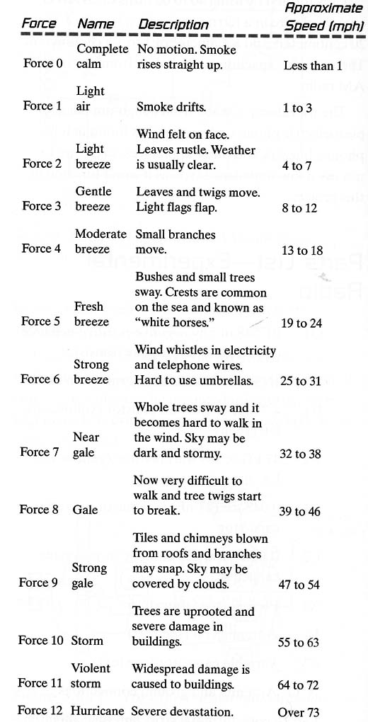
Anemometer
Because the voltage produced by the eolic generator is proportional to the speed of the wind, you can use this project as a simple anemometer, a device used to measure only the speed of the wind. Figure 15 shows how you can use your eolic generator as an anemometer.

You can modify the system to measure the wind that is powering the motor by using small paper cups (see Figure 16).

The meter is an analog galvanometer. P1 is adjusted according to a reference for the speed of the wind. The Beaufort scale, given in the following table, allows you to determine the approximate speed of the wind by its effects.
Anemometer
D1 - 1N4002 silicon rectifier diode
C1 - 100 µF- 16-Volt electrolytic capacitor
M1 - 0 to 200 µA or 0 to 1 mA analog meter
R1 - 4.7 k ohm - 1/8-watt resistor (yellow, violet, red)
P1 - 100 k ohm - trimmer potentiometer
Plastic box, wires, solder, etc.
Cross Themes
Alternative energy sources are today being studied in many schools, beginning in elementary school science courses, all the way to physics and geography at the university level.
Both the most basic and the most complex versions (such as the one with a voltage regulator) of the colic generator can be used when experimenting with a variety of alternative energy sources. It can be used to illustrate the following crossover themes:
To show how the power of the wind can be converted into electrical energy
To study the amount of energy that can be generated by a particular source
To show how dynamos work
To compare one energy source with other sources in terms of pollution, efficiency, and so on
Other Circuits and Ideas
As explained previously, when building eolic generators you should not be limited to small DC motors only. Other generators with higher performance in energy conversion can be powered by wind energy.
In particular, we suggest a bicycle dynamo that comes in a variety of styles, starting with the unregulated units that are intended to power only lamps to the sophisticated units that have electronic circuits to charge the batteries of cellular phones.
These bicycle dynamos need more speed and power to be used but can generate much more energy, 6 to 15 volts with a current of up to 2 amps in some cases. They are a good solution for the evil genius who wants a greater challenge beyond those given here.
Voltage Regulator
Sensitive electronic applications can be damaged if powered by a source presenting voltage changes, and this is exactly what our eolic generator can cause.
Radios, calculators, and clocks are examples of voltage-sensitive devices. To power those devices, it is important to add a voltage regulator. Figure 17 shows two voltage regulators.
The first circuit is a low-power version recommended for use with devices pulling less than 5 mA.
The second circuit can be used with devices pulling up to 1 amp.
High Voltage Inverter
If your eolic generator is powerful enough to source voltages between 5 and 12 volts with currents higher than 100 mA, you can power a fluorescent lamp using an inverter.
An inverter, such as the one shown in Figure 18, can convert low continuous voltages into high alternating voltages.

The high voltage, when applied to a fluorescent lamp, can ionize the gas inside to make it glow. The simple fluorescent lamp inverter shown in the figure can be used with lamps of 5 to 20 watts, even the ones that no longer function when powered from the AC power line.
The lamp will not glow with the original brightness but will have a reduced glow that is dependent on the amount of energy supplied by the colic generator.
The transformer can be any power transformer with a 117 VAC primary coil and a 5- or 6-volt center tap (CT) secondary coil, rated to currents in the 50 to 300 mA range.The transistor must be mounted on a heatsink, and P1 adjusts for frequency for the best performance matching the characteristics of the transformer with the generator.
Caution! Do not attempt to power any electronic device with this circuit. The output voltage is not a sine wave and the frequency is not 60 Hz.
Inverter
Q1 - BD135 or equivalent NPN medium-power transistor
T1 - Transformer (see text)
R1 - 1 k ohm X 1/8 - Watt resistor (brown, black, red)
P1 - 10 k ohm - trimmer potentiometer
C1 - 0.047 µF ceramic or polyester capacitor
C2 - 0.1 µF ceramic or polyester capacitor
L1 -Fluorescent lamp, 5 to 20 watts
PCB or terminal strip, heatsink for the transistor, plastic box, wires, solder, etc.


