As we have know, the windings of a stepper motor must be energized properly to achieve correct operation. This means that, When using a stepper motor, you,ll need to know not only the electric speciñcations for this kind of device but also the mechanical specifications.
The following are the most important.
VOLTAGE AND CURRENT
In most cases, stepper motors have Voltage ratings of 5, 6, or 12 V. Unlike conventional DC motors, is not recommended that you overdrive the windings of a stepper motor. Overvoltages of more than 30 percent of the rating can burn the windings.
The current ratings depend on the application (size and torque). Common types can draw currents in the range from 50 mA to more than 1 A. The higher the current and voltage, the higher the torque.
When designing a power supply for an application using a stepper motor, it is important to consider that the current ratings are given per winding. So the power supply must be able to supply at least double the current per winding, or eight times the current per winding in a four-phase type.
SEQUENCE
Although most stepper motors use one of the two sequences described in other articles, some units use different sequences. When using such units, you must determine the sequence of pulses that produces correct operation.
STEP ANGLE
When a pulse in the sequence is applied to the motor, it advances one step. This means that the shaft moves a predetermined number of degrees.
Depending on the type of motor, this can vary in the range between 08° and 90°. In a 90° stepper motor, four pulses drive the shaft to complete one turn, as shown in Fig. 1.

But it is more common to find stepper motors with step angles of 1.80. This means that you must apply 200 pulses to the control circuit to drive the motor one complete turn.
PULSE RATE
The pulse rate determines the speed of the motor. If you are using a 1.8° step angle motor, and you apply 200 pulses per second, the motor will run at l rotation per second or 60 rotations per minute (60 rpm). Given the step angle, it is easy to calculate the rpm.
Stepper motors are not intended for high-speed applications. The top recommended speeds are in the range of 2 or 3 turns per second, or 120 to 180 rpm. It is important to remember that, in this kind of motor, the torque drops as the speed increases.
TORQUE
The torque produced by a stepper motor is not very high. A typical stepper motor can provide only a few grams per centimeter when running. This means that, in applications where high torque is needed, gearboxes must be added.
Since torque falls with speed, it is important to use these motors in low-speed modes. Refer to other articles in the site for information about torque measurement.
BRAKING EFFECT
If you maintain the current flow in a winding after a pulse has been applied, the stepper motor can’t continue to turn. The shaft becomes locked as if you applied a brake. A circuit that maintains the current in a winding to hold a particular position is, in effect, an electronic brake for the stepper motor.
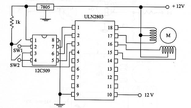
Next figures show the following circuits used to control stepper motors:


")

ICS RECOMMENDED FOR STEPPER MOTORS DRIVERS
The following table provides information about other transistor arrays and power stages that are recommended for stepper motor drive circuits.