

What Are
SCRs (Silicon Controlled Rectifiers) or Silicon Controlled Diodes are semiconductor components of the Thyristor family. As shown in Figure 1, we have its symbol and structure. The SCR comprises four layers of semiconductor materials having three terminals (gate, anode and cathode).
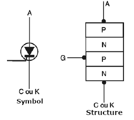
A positive pulse applied to the gate drives the device into a conduction state, after which intense electric currents between the anode and cathode can be controlled.
What To Test
For static tests with continuity probes and multimeters, we can consider an SCR equivalent (in structure) to two transistors connected, as shown in Figure 2.
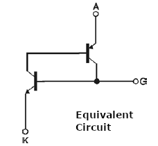
We can then test the continuity of the junctions, checking if they are good or short-circuited. However, the best tests are performed with appropriate circuits, including the oscilloscope, to visualize its characteristic curve.
Instruments Used
• Continuity tester
• Test lamp
• Multimeter
• Test circuit
• Oscilloscope and associated circuits
When using the test lamp, we must only ensure that the applied electric current does not exceed the maximum supported by the component.
The Tests
There are several standard tests used to prove the condition of low or medium power SCRs. We describe some of these tests below.
a. Junctions Proof of Continuity
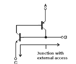
What is tested in this case is the condition of the junctions. Eventually, we can find out if there is a short circuit between the anode and the cathode. We start with the equivalent circuit of two transistors, observing that the only junction directly proved with polarization tests in both directions is the junction between the gate (G) and the cathode (C), as shown in figure 3.
Procedure:
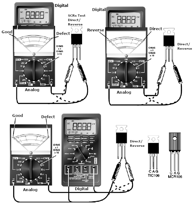
a) Adjust the multimeter on an intermediate resistance scale (Ohms x10 or 0hms x100). If it is a digital multimeter, then use the 2,000 Ohms or 20,000 Ohms scale. For the continuity tester, just get it ready.
b) Identity the SCR's terminals and measure the combined resistances between them. The SCR must be out of the circuit.
c) Compare the obtained measures with those shown in Figure 4. Note that only one measure should result in low resistance.
Figure 4 shows the test results.
Analysis Of The Results
If the resistances and continuities are those indicated in Figure 4, then the SCR is probably good (this is not a conclusive test). However, if more than one resistance is low or if all the measures are of high resistance, then, undoubtedly, the SCR is damaged.
Notes
We note that for the high-power SCRs, for instance, the tests are also valid, but the low test current of the multimeters can hinder the results. It will be interesting to have a good SCR of the same type for comparisons. Consulting the component's datasheet can help in this case.
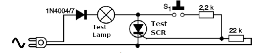
b. Using A Test Lamp
The test with a test lamp simulates the operation of the SCR, and the reader must use a 2k2 Ohms resistor, a 22k Ohms resistor and a 1N4004 diode for the tests on the 110 V mains. Only 30 A with working voltages from 200 V SCRs should be tested.
For a lamp connected to the 220 V mains, only 350 V or more working voltages and currents of the same range as the previous case SCRs should be tested. The trigger current will be in the order of 50 mA. Thus, SCRs that require a higher trip current cannot be tested with this circuit.
The test circuit is shown in Figure 5.
Procedure
a) Initially identify the SCR terminals by connecting only the lamp and power supply. Leave the gate terminal free and connect the circuit to the mains.
b) Then, for a moment, turn off the power and connect the diode and the 470 Ohms resistor.
c) Observe what happens to the lamp.
Test Analisys
Without the diode and the 470 Ohms resistor in the circuit, the lamp should remain off. By connecting the resistor and diode, the lamp should light at approximately half of its maximum brightness (the SCR is a diode and, therefore, a half-wave device). If this happens, the SCR is fine.
If, when placing the SCR in the circuit without the diode and the resistor and the lamp already light up at maximum brightness, then the component is short-circuited. If, when placing the diode and the 470 Ohms resistor, the lamp does not light up, then the SCR is damaged.
Notes: Depending on the SCR trigger current, it may be necessary to reduce the value of the resistor for testing. If nothing happens with a 470 Ohms resistor, try a 270 Ohms or even a 150 Ohms resistor.
c. Trigger Current Measurement
Figure 6 shows how to implement a simple test circuit for determining the trigger current of the SCR, especially ICT and equivalent models, of up to 30 A and with trigger currents up to 20 mA.
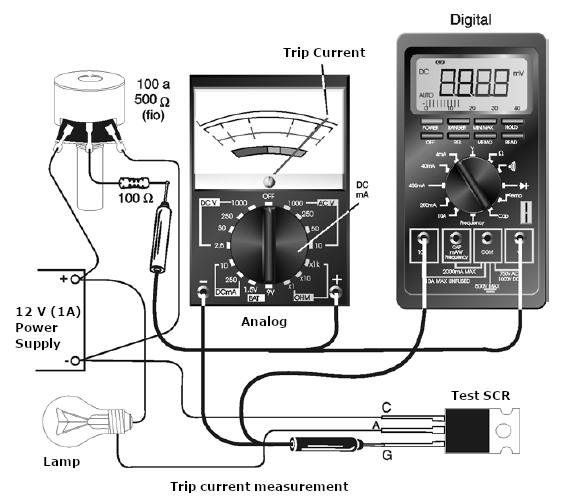
Procedure
a) Identify the terminals of the SCR to be tested, then connect the component to the circuit.
b) Set the potentiometer to the minimum position. Turning on the circuit, observe the test lamp.
c) Then, act on P1, observing the indicators and the moment when the lamp lights up.
Test Analisys
The lamp must remain off when connecting a good SCR to the circuit and turning on the power. If the lamp lights up, then the SCR is short-circuited. Reaching the position where the lamp lights up, we can read the trigger current on the multimeter.
Notes: In this case, we can reduce the gate resistor to test an SCR that needs a higher trip current. Values between 150 Ohms and 330 Ohms can be experimented with.
d. Using The Oscilloscope
We can use a test circuit to visualize the triggering conditions of an SCR and thus also check its status. The circuit is shown in Figure 7.
In this case, we simulated in Multisim 9 a conventional power control that the reader can build, without the need of an oscilloscope, for SCRs with a trigger current of 50 mA and both 110 V and 220 V mains.
A 100 k Ohms potentiometer can be connected in series with the resistor to control the lamp's brightness. You can also replace the diac with a standard neon lamp. For lower voltage SCRs, use an appropriate AC power supply. In that case, the diac must be able to trigger with the test voltage.
Procedure
a) Set the oscilloscope to show 60 Hz signals with an amplitude of approximately 150 V.
b) Connect the circuit as demonstrated to have the waveforms shown in Figure 8.
c) By changing the value of R1, the modification of the semi-cycle of the conducted signal must be obtained.
If the SCR is not in good condition, the waveforms will not be obtained. Some waveforms indicating a faulty SCR are shown in Figure 8.
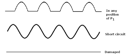
Notes: This circuit is not isolated from the mains, so the utmost care should be taken that their live parts are not touched or come into improper contact with the test equipment. A good careful measure for working with this test circuit is to use an isolation transformer.


