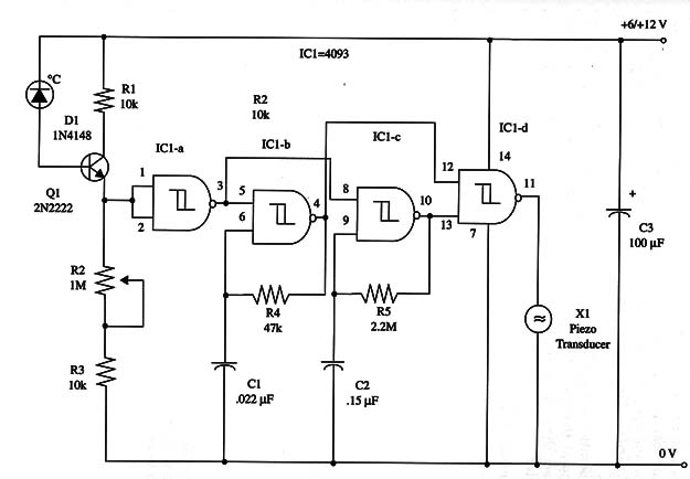
The sensor is a common silicon diode, but it suggests the possibility of another project using a thermistor. Swapping the positions of R1 and Q1 with the positions of R2 and R3, we get an over-temperature alarm.
The circuit produces an intermittent sound generated by two oscillators. IC1-a is an inverter that controls IC1-b and IC 1-c. IC1-b is a very low-frequency oscillator that determines the modulation rate of the second oscillator.
The second oscillator is formed by IC1-c, and its frequency is given by R5 and C2. The produced audio tone can be altered by varying both R5 and C2 within a large range of values, as described in other projects in this section.
Power comes from a 6 V to 12 V power supply. For a portable application, you can use small 9 V batteries. The current drain is only about 0.5 mA when the tone is off. With the tone on, the current drain reaches 5 mA.
Powerful output stages can be used for applications where a higher audio level is needed.
A schematic diagram of the Under-Temperature Alarm is given in Fig. 1.

Proper positioning of the polarized components must be observed, including diode D1, which is used as a sensor. This sensor can be placed at a distance from the device using common wires, depending on the intended application.
You be careful to avoid humidity and not allow water to fall onto the sensor, which can cause problems with the circuit operation. X1 is a piezoelectric transducer or a crystal earpiece.
For more powerful audio outputs, you can use a transistorized output stage driving a loudspeaker, as described in other projects in this book.
Operation is adjusted by R2. Set this potentiometer to produce the sound at the desired temperature.
For a precise adjustment, you can replace the common trimmer potentiometer with a multi-turn potentiometer.
IC1 - 4093 CMOS integrated circuit
Q1 - 2N2222 N PN general purpose silicon transistor
D1 - 1N4148 general purpose silicon diode
X1 - Piezoelectric transducer or crystal earpiece, Radio Shack 27 3-073 or equivalent
R1 - 10,000 ohm, 1/4 W, 5% resistor
R2 - 1,000,000 ohm potentiometer (trimmer)
R3 -10,000 ohm,1/4 W, 5% resistor
R4 - 47,000 ohm, 1/4 W, 5% resistor
R5 - 2,200,000 ohm, 1/4 W, 5% resistor
C1 - 0.022 µF ceramic or metal film capacitor
C2 - 0.015 µF metal film or ceramic capacitor
C3 - 100 µF, 16 WVDC electrolytic capacitor


