

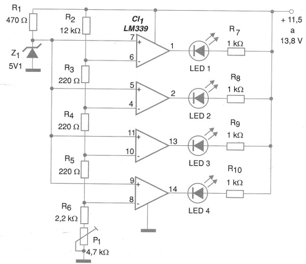
In it, the four voltage comparators of an LM339 integrated circuit are configured to activate a scale of 4 LEDs in four different voltages determined by the trimpot setting.
The trigger points of each comparator are determined by a reference zener diode With a voltage of 12.7 V or more in the circuit the four LEDs are lit indicating battery charged. The drive steps of the circuit are approximately 0.3 V which means that, with less than 11.7 V, the four LEDs will be off. The values ??of the reference scale resistors can be changed to modify this scale. For example, 470 ohm resistors will result in steps of approximately 600 mV.
The only circuit setting is at P1 so that the 4 LEDs light when the voltage applied to the circuit is 12.7 V.
Semiconductors:
CI-1 - LM339 - integrated circuit
Z1 - 5.1 V x 400 mW - zener diode
LED1 to LED4 - Common LEDs
Resistors: (1/8 W, 5%)
R1 - 470 ohms
R2 - 12 k ohms
R 3, R 4, R 5 - 220 ohms
R6 - 2.2 k ohms
R7, R8, R9, R10-1k ohms
P1 - 4.7 k ohms - trimpot
Several:
Printed circuit board, wires, solder, etc.


