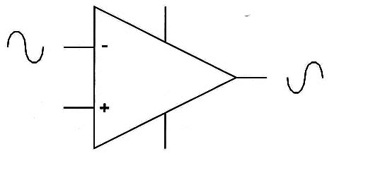
The ideal operational amplifier has an infinite input impedance and a null output impedance. The real types have a very high input impedance of many megohm and a very low output impedance (some ohm to hundreds of ohm).
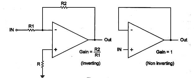
The gain of an operational amplifier or the number of the times the output voltage is higher than the voltage applied to the input can be programmed by a feedback circuit as shown in Figure 2.

The higher gain is achieved when the feedback is infinite and typically ranges from 10,000 to 1,000,000 in the common types.
The lowest gain is achieved when the feedback loop is a zero ohm resistance and is one.
The configuration with a voltage gain of one is called voltage follower.
In a voltage follower the output voltage is the same as the input voltage.
Despite this, the difference in impedance between the input and output makes the circuit an amplifier with a very high current gain.
Operational amplifiers can be found in a large number of types, sizes, and presenting a large range of electrical characteristics (input and output impedances, power supply voltages, gains, type of transistors found inside as FETs or bipolars, operation frequency range, etc.).
Symbol
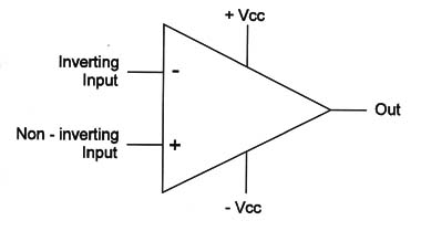
Figure 3 show the symbol adopted to represent an operational amplifier. They generally look the same as other ICs.

Notice that some lCs exist that contain two or more operational amplifiers.
In some cases we can also find terminals where additional components are plugged. These external components are used to add special characteristics to the circuit such as frequency compensation.
Specifications
The operational amplifiers are indicated by a part number according to a code adopted by the manufacturer. Normally a group of letters is used to identify the manufacturer - MC = Motorola, SN 2 Texas Instruments, LM = National Semiconductor, etc.
From the part number or consulting data sheets and/or handbooks it is possible to access the electrical characteristics of each device. These characteristics are:
A. Open loop gain-The gain is determined by the internal circuit and is specified the maximum gain or the “open loop” gain where no feedback is used. The values can range from 1000 to 1,000,000 in common types. The gain of an Ao can be abbreviated by G.
B. Power supply voltage range-This specification indicates the range of voltage that the operational amplifier needs for correct operation. It can range from 1.5 V to more than 40 V.
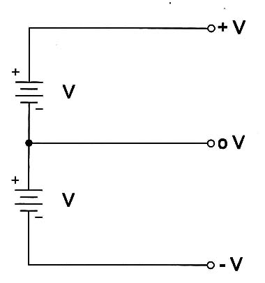
At this point it is interesting to observe that in many applications the AO needs a symmetrical or double power supply. It is a power supply where a positive and a negative voltage referred to the ground (0 V) must be generated as shown in Figure 4.

In some documents, datasheets, and diagrams it is common to refer the power supply voltage for an AD as 6-0-6 V, +6, -6, 0 V, +6/-6/0 V or 6+6 V if it needs a symmetrical supply as the one shown in Figure 4.
C. Gain x Bandwidth-The gain of an operational amplifier falls at the same time the signal frequency increases. The frequency band is limited by the point where the gain falls to one; this determines the gain bandwidth product. Common operational amplifiers can operate in frequencies from 1 or 2 MHz to up to some hundreds megahertz.
D. CMRR-lf two signals with the same amplitude and phase are applied, one to the inverting input and the other to the noninverting input of an operational amplifier they must be cancelled and the output will be zero. In practice, due to small differences in the internal components, this is not possible and some part of the signal is not cancelled, which then appears in the output. How efficient is the AO when canceling a signal in this operation mode is given by a specification called Common Mode Rejection Ratio or CMRR. This specification must be as high as possible and is indicated in decibels (dB). Common types have CMMR as high as 90 dB and more.
Where they are found
Many appliances use operational amplifiers in the integrated circuit form. They normally are common types such as the 741, CA3140, TL080, TL081, and many others that are easily found in any electronic components shop.
Special operational amplifiers can be found driving step motors or other devices, but in general, they can be found at a dealer by part numbers, too.
The basic function of an operational amplifier in many circuits is the amplification of signals coming from sensors, transducers, or other sources, driving them to powerful output stages or circuits that must work with signals having a larger amplitude.
Testing
In many applications the operational amplifier can be tested measuring the voltages in their pins. If the voltages are altered, and the components plugged into it are good, the problem will be certainly in the OA.
Another way to test is using a special probe circuit.


