The preamplifier must be installed between low-impedance transducers such as microphones, pickup coils, sensors, and other signal sources and the medium high-impedance input of an audio amplifier or other equipment.
The circuit can be used with transducers or signal sources with impedances ranging from 2 to 500 ohm.
The power supply is a 9 V battery, and power consumption is very low. We don’t recommend a power supply plugged to the ac power line, as hum can be introduced if the output is not well filtered.
How it Works
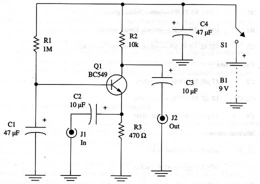
The circuit is formed by a single common-base stage with an NPN high-gain transistor. The low-impedance audio source is plugged into the emitter of the transistor where the signal is applied. The amplified signal appears in the collector from where it can be transferred to the output via C3.
Bias is given by R1 and decoupling by C1. R3 fixes the input impedance and also the gain. This resistor can be replaced by others in the range between 47 and 1 k Ω, depending on the impedance of the signal source.
The reader must experiment with different values of R3 to get better performance, which depends on the signal source.
Assembly
The circuit is shown in Fig. 1.

Keep the wires short, and use a shielded cable for the output signal. The input and output jacks are chosen to match the signal source and the input of the amplifier or tape recorder. The unit can be housed in a small plastic box with the battery.
The components are not critical, and equivalents of the indicated transistor can be used for experimentation.
Using the Circuit
The circuit is placed between the audio source and the input of the amplifier or tape recorder. The output must be plugged to the AUX or other high- or medium-impedance input of the amplifier.
For example, a pickup coil can be used if you want to try to intercept voices carried over a telephone line. Place the pickup coil near a common telephone device, adjusting for a position that gives the best results. The hum filter described in other project can be useful in this experiment to block any 60 Hz noise that may be present in the line.
Suggestions
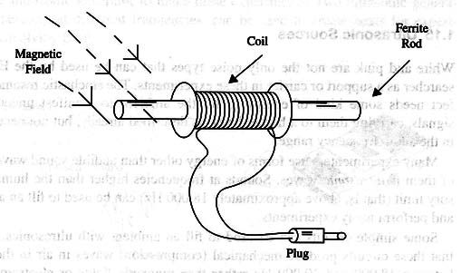
- A pickup coil can be used as the transducer to experiment with noises occurring in the ambient magnetic field. This is shown in Fig. 2.

The coil is formed by 1,000 to 10,000 turns of 32 to 34 AWG wire wrapped around a ferrite rod.
You can also use the primary of a small transformer as a pickup coil. Remove the core and place a ferrite rod inside it.
- Small loudspeakers and low-impedance earphones can be used as microphones with this preamplifier.
Semiconductors
Q1 - BF549, general-purpose silicon NPN transistor-low noise
Resistors
R1 - 1 M ohm, 1/8 W, 5%-brown, black, green
R2 - 10 k ohm, 1/8 W, 5%-brown, black, orange
R3 - 470 ohm, 1/8 W, 5%-yellow, violet, red (see text)
Capacitors
C1 - 47 µF, 12 WVdc, electrolytic
C2, C3 - 10 µF, 12 WVdc, electrolytic
C4 - 47 µF, 12 WVdc, electrolytic
Miscellaneous
J 1, J2 - Input and output jacks
S1 - SPST, toggle or slide switch
B1 - 9 V battery
Printed circuit board, battery clip, plastic box, shielded cable, wires, solder, etc.


