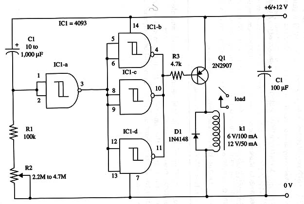
Using a PNP transistor, the relay is powered when IC-b, c, and d outputs go to the low level at the end of the adjusted time delay.
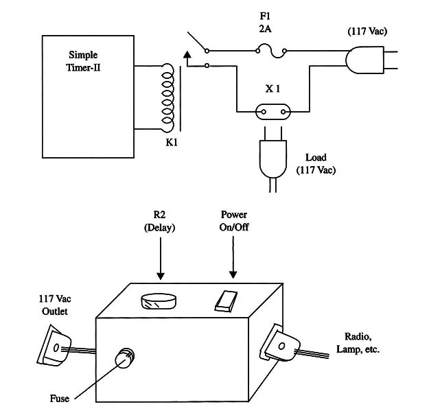
You can use this timer as part of other, more complex projects or as an easy-to-use timer to control appliances from the ac power line, adding some components as shown in Fig. 1.

Using a 1 A relay (e.g., Radio Shack mini SPST relay), you can control ac loads up to 100 W.
The circuit can be powered by AA cells or, if you prefer, from an ac power supply. (See in the introduction of this book for some suggestions with regard to power supplies.)
A schematic diagram of the Simple Timer II is shown in Fig. 2.

The proper position of the polarized components (diode and electrolytic capacitors) must be observed.
To operate the unit, set the time delay by R2 and turn on the power supply.
After the adjusted time delay, the relay will be energized, acting on the load.
IC1 - 4093 CMOS integrated circuit
Q1 - 2N2907- NPN general purpose silicon transistor
D1 - 1N4148 general purpose silicon diode
K1 - 12 Vdc, 43 mA, 280 S2 mini DPDT or SPST relay, contacts rated to 1 A (Radio Shack 275-249 or equivalent) or a 6 V unit (see text)
R1 - 100,000 ohm, 1/4 W, 5% resistor
R2 - 2,200,000 ohm potentiometer
R3 - 4,700 ohm, 1/4 W, 5% resistor
C1 - 10 µF to 1,000 µF, 12 WVDC electrolytic capacitor (see text)
C2 - 100 µF, 12 or 16 WVDC electrolytic capacitor


