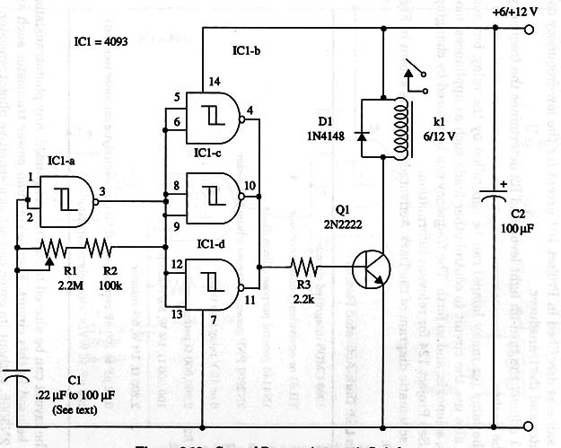
On and off intervals can be adjusted from a few seconds to several minutes, according the intended application, by varying the value of Cl. With values between 0.22 and 0.47 µF, we have time intervals that can be adjusted from a fraction of a second to a few seconds.
Using a 100 µF capacitor, we get time intervals ranging from 1 or 2 minutes to 7 or 8 minutes.
Current requirements of the load are limited by the relay’s contacts. You can both use a 1 A DPDT 12 V mini relay (Radio Shack 275-249) or a 10 A SPDT mini (Radio Shack 275-248).
Relays with coils rated from 6 V can also be used in this project. This, of course, reduces the power supply voltage to the same value.
The circuit can be powered from battery or ac-to-dc converters. Current requirements are basically determined by the relay.
A schematic diagram of the General Purpose Automatic Switch is given in Fig. 1.

This layout uses a DPDT relay, but you can change it to accommodate a different relay.
IC1 - 4093 CMOS integrated circuit
Q1 - 2N2222 NPN General purpose silicon transistor
D1 - 1N4148 general purpose silicon diode
K1 - 6 or 12 V relay (see text)
R1 - 2,200,000 Ω - potentiometer
R2 - 100,000 Ω, 1/4 W, 5% resistor
R3 - 2,200 Ω, 1/4 W, 5% resistor
C1 - 0.22 µF to 100 µF ceramic, metal film or electrolytic capacitor (see text)
C2 - 100 µF, 16 WVDC electrolytic capacitor


