

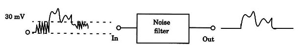
This circuit can be used to eliminate the background noise on a tape, revealing voices and other sounds more easily. It will be installed between the tape recorder and an amplifier as shown in Fig. 1.
The basic idea is the use of a noise source to add energy to the undetectable voices (see stochastic resonance), increasing their level when taped. Then, when listening to the tape, the researcher can reduce or eliminate the background noise to more easily find the voices.
Operation
The circuit is an amplifier stage that cuts the signals between two silent zones or between two detectable signals. This means that this circuit cuts the signal when the ratio of signal to noise falls bellow a certain level.
With the values shown in the diagram of Fig. 2, the circuit cuts signals with amplitudes below 30 mV.

If a signal with an amplitude greater than 30 mV ispresent, operational amplifier Al has a high enough output to bias Q1. This implies an increase in gain at the operational amplifier A2, and the amplified signals appear in its output.
When the amplitude of the input signal is below 30 mV, Q1 is not biased and the gain of the circuit is reduced to less than 1/40 of the initial value.
To operate with signals over 30 mV, it is enough to increase the value of R2.
Values between 10 k Ω and 100 k Ω can be used experimentally.
The gain of the circuit is determined by R7. Values between 100 kΩ and 1 M Ω can be used experimentally.
The circuit needs a symmetric, or two-voltage, positive/negative power supply as shown in Fig. 3.

Voltages between 9 and 15 Vdc can be used to power this circuit. Current drain is very low, less than 10 mA, allowing the use of batteries as power supplies.
Some operational amplifiers can be powered from lower voltages. The CA3140, for instance, can be powered from voltages as low as 3 V. IC1 and IC2 don’t need a heatsink, as the current drain is very low.
Assembly
The circuit can be mounted on a small printed circuit board and housed in a plastic box. Input and output jacks should be installed to match the output of the tape recorder and the input of the amplifier. The audio signals must be transferred to the circuit and from the circuit using shielded cables.
Any J FET operational amplifier such as the CA3140, TL071 or the dual TL072 can be used. The transistor specifications also allow equivalents such as the MPF102 or any J FET transistor. Note that the terminal placement of the MPF102 is different from that of the BF245.
As the circuit has a high-impedance input and high gain, special care with the signal cables is needed to avoid hum. As in the other cases, the hum (60 Hz noise picked up from the ac power line) can cover the noise as well as the voices recorded on the tape, compromising the experiments.
Using the Circuit
The circuit is placed between the signal source (tape recorder or other) and the amplifier as shown in Fig. 1. The circuit will cut noise, allowing some sound peaks through.
If no sound is heard, you must increase the output level of your tape recording, trying to find a level that will give the best voice detection results. Careful experimentation must be conducted to find the ideal point.
Notice that this circuit has a high-impedance output and input. This means that earphones, headphones, and loudspeakers can’t be driven directly from its output.
If the circuit tends to distort when plugged into the output of a tape recorder (monitor) add a 100 ohm resistor in parallel with the filter’s input.
Initial operation tests can be made using a tape with common content such as music or voice. Voice is recommended, as the intervals between words will engage the circuit, cutting the background noise.
Suggesfions
Alter the value of resistors R2 and R7 to change the performance to get the de- sired effects.
C3 determines the frequency characteristics of the circuit, and values between 100 µF and 1,000 µF can be used experimentally.
Replace R7 with a 1 MS! potentiometer, which can be used as a volume control.
R5 can also be varied using resistors rated between 100 kg and 1 M9 to alter the behavior of the noise detection.
Semiconductors
IC-1 - CA3140, TL071, or TL072; J FET operational amplifier
Q1 - MPF102, BF245, or equivalent; any J FET transistor
D1 -1N914, 1N4148, etc., general-purpose silicon diode
Resistors
R1 - 150 k Ω, 1/8 W, 5%-brown, green, yellow
R2 - 22 k Ω, 1/8 W, 5%-red, red, orange
R3 - 1M9, 1/8 W, 5% - brown, black, green
R4 - 10 k Ω, 1/8 W, 5%-brown, black, orange
R5 -1.2 M Ω 1/8 W, 5%-brown, red, green
R6 - 220 k Ω, 1/8 W, 5%-red, red, yellow
R7 - 470 k Ω, 1/8 W, 5%-yellow, violet, yellow
Capacitors
C1 - 0.15 µF, ceramic or metal film
C2 - 0.47 µF, ceramic or metal film
C3 - 220 µF, 25 WVdc, electrolytic
Miscellaneous
Printed circuit board, plastic box, input and output jacks, power supply, wires,
shielded cable, solder, etc.


