Obs. This project is part of my book Electronic Projects from the Next Dimension (2001).
Experiments
Some proposed experiments using this circuit include the following:
Try using the skin resistance data from the current meter to perform biofeed- back experiments.
Skin resistance can be associated with physiological and mental states in ESP and PK experiments. Changes in skin resistance during ESP trials can be detected and linked to results or mental states of the individuals under examination. In telekinesis and psychometry studies, the researcher can detect whether any change in the skin resistance of a subject occurs during the experiments.
The resistance of plants and organic solutions can be monitored with this circuit, detecting the influence of paranormal forces during experiments. Using your mind, try to alter the resistance of a water/vinegar mixture in a cup. As electrodes, use two pieces of bare wire, 10 to 12 cm long.
Attach the electrodes to a plant leaf and see if paranormal phenomena affect their resistance. Experiments in PK and ESP can be conducted using plants as sensors. (Clever Backster discovered that plants have some paranormal abilities by monitoring them with a polygraph. See the book, The Secret Life of Plants, by Peter Tompkins and Christopher Bird.)
Experiments involving pendulum action and changes in the skin resistance of a subject can be performed. Changes can indicate some alteration in physiological or mental states that is unseen by the naked eye or other detection processes.
The circuit can be used to detect many other paranormal phenomena based on the electrical resistance changes of living beings and things. The skin resistance of “sensitive” subjects can change during paranormal manifestation. This applies to the resistance of living things such as plants and live solutions (lactobacillus, bacteria colonies, etc.).
How It Works
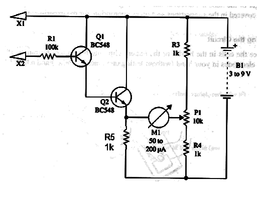
Two transistors in a Darlington configuration form a dc amplifier. The current is drawn from the two electrodes placed on the skin of a person. Any change in skinresistance will produce a variation in the resistance between the collector and emitter of Q2. Q2, R2, R3, R4, and P1 are wired to form a Wheatstone bridge.
The zero (null) detector in this bridge is a sensitive current meter.
By placing the electrodes on the skin of a person, it is possible to zero the bridge using P1. Any change in skin resistance will be transposed into a strong change in the equilibrium of the bridge, causing current to flow through the meter.
Assembly
Figure 1 shows the diagram of the lie detector or polygraph.

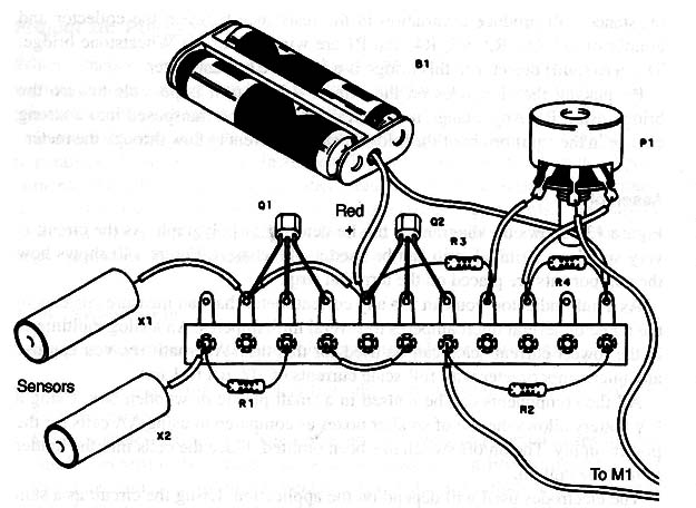
As the circuit is very simple, a terminal strip can be used as the chassis. Figure 2 shows how the components are placed on the terminal strip.

As a null indicator, you can use any current meter that can measure currents in the range of several microamperes to several milliamperes. An analog multimeter in the lowest current scale can be used for this task. Alternatively, you can use any microamperimeter with full-scale currents of 100 µA to 1 mA.
All the components can be housed in a small plastic or wooden box. Using a I 9 V battery allows the use of smaller boxes as compared to using AA cells for the power supply. The on/off switch has been omitted. Place the cells into the holder to turn the unit on.
The electrodes used will depend on the application. Using the circuit as a skin resistance monitor or polygraph, the electrodes can be two metal rods. The rods have a length of 10 cm and a diameter of 1 or 2 cm. The subject must keep the electrodes in his hands, using constant pressure.
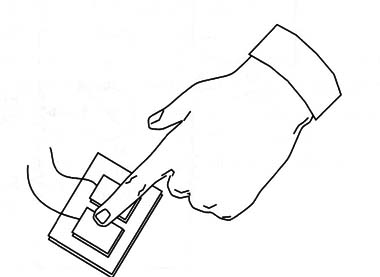
Another option for the electrodes is to use two small metal plates where the finger or the hand is placed, as shown in Fig. 2.

Other electrode configurations are covered in the suggestions section as appropriate for the experiments.
Using the Circuit
Place the cells in the holder or the battery clip onto the battery terminals. Place the electrodes in your hand (without letting one touch the other) and adjust P1 to show a center scale deflection.
Do not alter the pressure on the electrodes, and observe the needle indication on the meter. Any change in skin resistance will be shown by a movement of this needle.
In experiments involving plants, the electrodes can be two small metal plates fixed to a leaf by a clip. Don’t use a clip that produces excessive pressure, as it can damage the leaf and alter the results of the experiments.
Suggestions
You can monitor the bioactivity of plants by placing two electrodes on a plant leaf. Experiments involving telekinesis or the Backster ef- fect can be performed using this configuration. Try to change the plant’s physiological activity (detected by this device) by concentrating your mind on it or using it as a target in ESP or radiesthesia experiments.
In plant experiments, the electrodes can be two pieces of rigid wire placed in the flower pot with the plant.
The two transistors can be replaced by one low-power N PN Darlington transistor such as the BC517.
If you place two wires in a glass cup, you can monitor any kind of solution. Adjust P1 to have a half-scale deflection. You then can detect changes in the resistance due to paranormal phenomena. Use a solution with biological components (bacteria or lacto bacillus, for instance) and see how it can react in ESP or telekinesis experiments.
Semiconductors
Q1, Q2 - BC548 or equivalent general-purpose NPN silicon transistor
Resistors
R1 - 100 k Ω, 1/8 W, 5%-brown, black, yellow
R2 - 4.7 k Ω, 1/8 W, 5%-yellow, Violet, red
R3, R4, R5 - 1 k Ω, 1/8 W, 5%-brown, black, red (4.7 k Ω - yellow, violet, red-for 9V supply)
Miscellaneous
P1 - 10 k Ω potentiometer (47 k Ω for 9 V battery)
M1 - 50 to 200 µA current meter, zero in the center of the scale (see text)
B1 - 3 to 9 V, AA cells or battery
X1, X2 - electrodes (see text)
Terminal strip, cell holder or battery clip, box, knob, Wires, solder, etc.


