Obs.: this circuit was originally written to be included in my book Electronic Projects from the Next Dimension (2001).
The circuit described here is ideal to perform both ESP experiments and PK as, in the first case, the subject must use his mind to guess what number has been chosen by the circuit and, in the second case, he must try to predict what number is about to be chosen by the circuit.
A principal advantage of this circuit is that it is powered from a 9 V battery and can be used in any convenient location. The circuit can be used in several experiments as suggested below.
Experiments
The researcher can use the device to choose a number that he does not yet know and make tests with subjects who try to guess the number using ESP.
The subject can try to control what number is chosen by the circuit in psychokinesis experiments.
In radiesthesia experiments, the device can be used to determine if the pendulum activity can alter the number chosen by the circuit.
How It Works
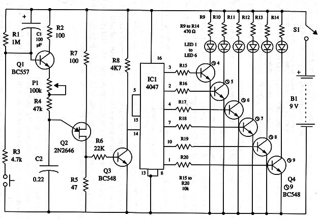
Q1, Q2, and Q3 form an oscillator that is programmed to produce a random number of pulses when S is pressed and released. The secret of this circuit is that It does not stop the circuit when S is released, avoiding the influence of the subject in the selected number of pulses.
When S is released, the oscillator’s frequency slows down until it stops some seconds later. The time span between the instant in which S is released and the circuit stops presenting random numbers is determined by C1 and R1. These components can be changed to suit the experiments.
Now, let us see in detail how this stage operates. When S1 is pressed, C1 charges with the power supply voltage biasing Q1. Q1 controls the relaxation oscillator formed by a unijunction transistor (UJT). When biased at the moment in which S is pressed, Q1 starts with the UJT oscillation at a frequency adjusted by R1 and basically determined by C2. These components determine how fast the numbers will run in the sorting process.
The pulses produced by the UJ T are amplified by Q3, driving a decade counter formed by the CMOS IC 4017. In this application, the counter is programmed to count up to six, meaning that the device can generate one of six numbers. If necessary, the reader can alter the circuit to count up to other numbers (between 2 and 10).
When receiving the pulses, the outputs of the 4017 go to the high logic level in sequence, driving transistors Q4 to Q9. As a load, these transistor use LEDs, but the circuit can be altered to drive small incandescent lamps (up to 50 mA).
When the last output goes to the high logic level, the circuit is reset and, in the next pulse, the first output again comes to the high logic level, driving the corresponding LED. This means that, as high as the number of pulses can be, there is always one LED remaining high after the cycle.
To avoid stopping the circuit when S is released, we have the capacitor C1 in the circuit. When S is released, C2 needs several seconds to discharge through the transistor, maintaining it in conduction, and so the oscillator remains on. As long as the capacitor discharges, the resistance between the emitter and collector of Q1 increases, and then the frequency of the oscillator falls.
The final effect is the gradual reduction of the running speed of the LEDs until the moment in which only one of them remains on. This corresponds to the generated number. To start the process again, the reader has only to press and release S again.
Assembly
Figure 1 shows the random number generator’s diagram.

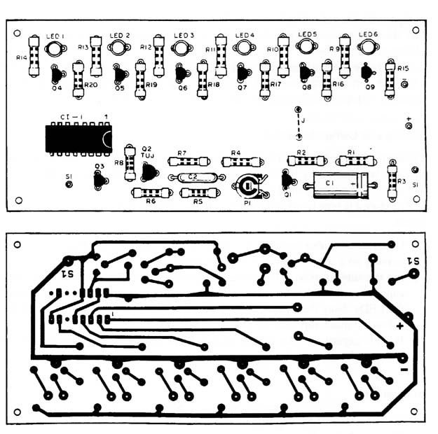
The components are placed on a small printed circuit board as shown in Fig. 2.

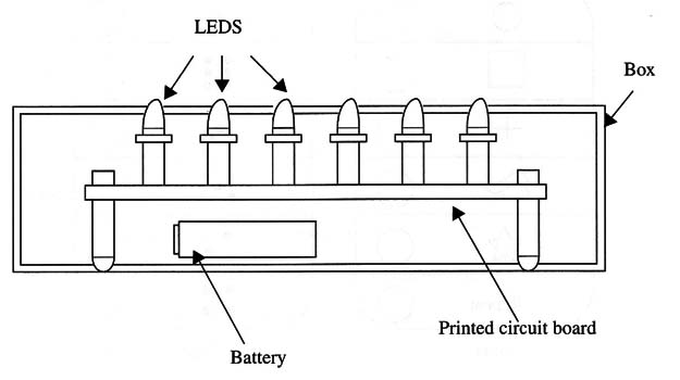
Common red LEDs are used. Keep the terminals long, as shown in Fig. 3.

This way you can fix the printed circuit board in the box and the LEDs will appear in the holes in the panel.
It is important to observe the position of polarized components such as the LEDs, electrolytic capacitors, bipolar and UJT transistors, and battery. The other components are not critical, and small changes in the original values will not affect the performance of the circuit. All of the components are placed inside a plastic or wooden box.
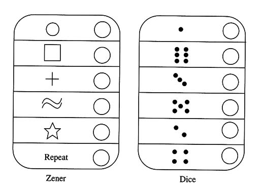
You can devise cardboard removable panels to be used in conjunction with the LEDs for various experiments. For example, zener cards, playing card symbols, numbers, letters, or other symbols can be used as shown in Fig. 4.

Testing and Using the Circuit
Connect a battery to the battery clip and press S. The LEDs will run at a speed that can be adjusted by P1. Make sure all LEDs glow in the process. Release S and wait a few seconds until one LED remains on.
The circuit is now ready to be used. You can conduct ESP experiments in many forms.
1. Generate a number without the subject knowing it, then ask him to write the number on a sheet of paper or guess it aloud.
2. Let the subject press S to generate the number, but cover the LEDs so they cannot be seen. After the subject tries to guess the number verbally, uncover the LEDs. Note the number of correct answers. S can be placed far from the subject to make sure that the number is hidden.
3. In a PK experiment, the subject presses S and releases it. He then tries to use his mental powers to dictate the generated number.
Suggestions
Use IR LEDs in ESP experiments. An IR detector can be used to see which LED is on during the experiment.
Alter C1 to change the length of the number generation process. Greater values increase the time. Values between 22 µF and 1,000 µF can be used experimen- tally.
Alter C2 to change the speed of the LEDs. Smaller capacitors will increase the speed. Values between 0.047 and l pF can be tested.
In PK or ESP experiments, resistor R1 can be increased to 22 k9, Cl can be reduced to 0.1 µF, and you can replace S with a touch sensor. The circuit then can be controlled by skin resistance or by a plant attached to the sensor.
Semiconductors
IC1 - 4017 CMOS integrated circuit
Q1 - BC557 or equivalent general-purpose PNP silicon transistor
Q2 - 2N2646 unijunction transistor
Q3 to Q9 - BC548 or equivalent general-purpose NPN silicon transistors
LED1 - LED6 - Red common LEDs (see text)
Resistors
R1 - 1k9, 1/8 W, 5% - brown, black, green
R2, R7 - 100 Ω, 1/8 W, 5% - brown, black, green
R3, R8 - 4.7 k Ω, 1/8 W, 5% - yellow, violet, red
R4 - 47 k Ω, 1/8 W, 5% - yellow, violet, orange
R5 - 47 Ω, 1/8 W, 5% - yellow, violet, black
R6 - 22 k Ω, 1/8 W, 5% - red, red, orange
R9 - R14 - 470 Ω, 1/8 W, 5% - yellow, violet, brown
R15 - R20 - 10 k Ω, 1/8 W, 5% - brown, black, orange
Capacitors
C1 - 100 µF/ 12 WVDC, electrolytic
C2 - 0.22 µF, ceramic or metal film
Miscellaneous
P1 - 100 k Ω, trimmer potentiometer
S - Momentary contact, normally open switch
S1 - SPST, toggle or slide switch
B1 -9 V battery
Printed circuit board, battery clip, plastic or wooden box, wires, solder, etc.


