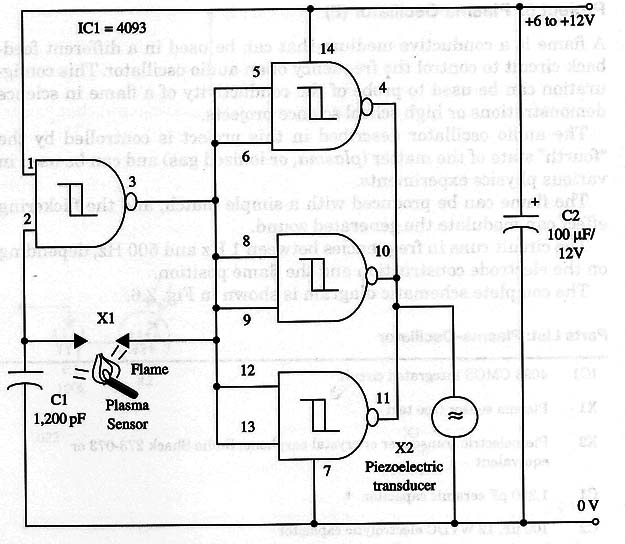
The audio oscillator described in this project is controlled by the “fourth” state of the matter (plasma, or ionized gas) and can be used in various physics experiments.
The flame can be produced with a simple match, and the flickering effect can modulate the generated sound.
The circuit runs in frequencies between 1 Hz and 500 Hz, depending on the electrode construction and the flame position.
The complete schematic diagram is shown in Fig. 1.

Two wires, one placed near the other with about 1 inch of bare length, form the plasma sensor. The flame should touch the two bare wires to allow the feedback to operate the oscillator.
Powerful output stages can drive other transducers such as loudspeakers.
101 4093 CMOS integrated circuit
X1 - Plasma sensor (see text)
X2 - Piezoelectric transducer or crystal earphone
C1 - 1,200 pF ceramic capacitor
C2 - 100 µF, 12 WVDC electrolytic capacitor
S1 - SPST switch
B1 - 6 to 12 V battery or power supply


