Obs. This project after be published in a Brazilian Magazine was included in my book CMOS Projects and Experiments (Newnes 1999)
The circuit is powered from a 6 V or 12 V supply, depending on the relay. With 12 V supplies, you can use a 1 A mini DPDT relay such as the Radio Shack 27 5-249. For heavy-duty loads, the indicated part is the 10 A SPDT relay, Radio Shack 275-248.
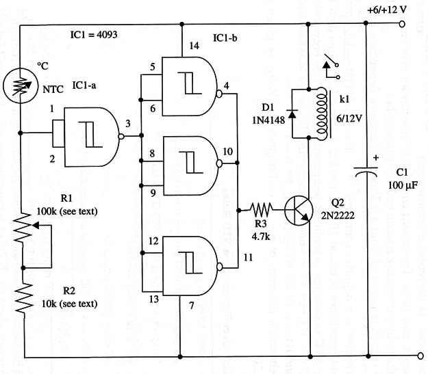
The sensor is a negative temperature coefficient (NTC) resistor with ambient resistance between 10 and 100 k ohm. R1 and R2 values depend on the N TC resistance at ambient temperature.
For NTCs between 10 and 47 k ohm, R1 is a 47 k ohm potentiometer and R1 is a 4.7 k ohm resistor.
For NTCs ranging from 47 to 100 k ohm, R1 is a 100 or 220 k ohm potentiometer, and R1 is a 10 k ohm resistor.
A schematic diagram of the Over-Temperature Relay is given in Fig. 1.

K1 is a mini DPDT relay that can be placed directly on the board. If you intend to use another type of relay, modifications in the layout should be made.
The sensor is placed as far as you want from the circuit. You can place the NTC in a greenhouse and the circuit into your home, for example.
Proper positioning of the polarized components must be observed.
To adjust the unit, set R1 to close the relay’s contacts at the desired temperature.
IC1 - 4093 CMOS integrated circuit
Q1 - 2N2222 NPN general purpose silicon transistor
NTC - Temperature sensor, 10 to 100 kg (see text)
D1 - 1N4148 general purpose silicon diode
K1 - 6 V or 12 V relay (see text)
R1 - 47 k ohm or 100 k ohm potentiometer (see text)
R2 - 4,700 ohm or 10,000 ohm, 1/4 W, 5% - resistor (see text)
R3 - 4,700 ohm, 1/2 W, 5% - resistor
C1 - 100 µF, 16 WVDC - electrolytic capacitor


