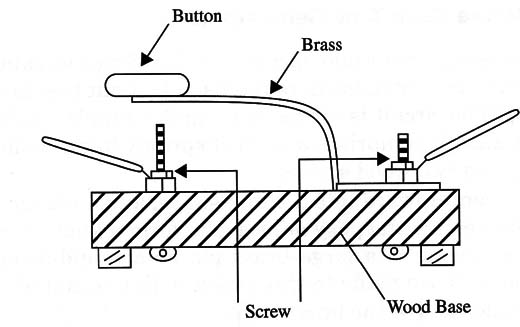
It comprises a strip of springy brass mounted on a wooden block, and two wood screws.
The brass is bent upward into a crank shape, and a plastic button is glued to the free end with epoxy adhesive to form a knob. Beneath the free end of the spring is a large brass pin or a round-headed brass screw. Key contacts are made to this screw, with one end of the screw securing the other end of the brass strip.
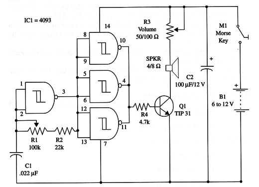
The tone is adjusted by means of R1, and volume by R3. The frequency of the free-running oscillator can be adjusted in a wide band, but output tones between 500 and 1,000 Hz are the most pleasant and the least tiring if you intend to practice for extended periods.
The complete schematic circuit of this device is shown in Fig. 2.

You can power this device with power supplies ranging from 6 V to 12 V, but with the 12 V power supply, the output transistor must be mounted on a heatsink.
All the components can be housed in a wooden box for better sound level, and portability.
A simple version can use a piezoelectric transducer directly connected to outputs b/c and d of the IC.
IC1 - 4093 CMOS integrated circuit
Q1 - TIP31 NPN silicon power transistor
SPKR - 4/8 9, 2-inch loudspeaker
M1 - Morse key (see text)
B1 - 6 V (four AA cells) or 9 V (battery)
R1 - 100,000 ohm, 1/4 W, 5% resistor
R2 - 2,000 ohm, 1/4 W, 5% resistor
R3 - 50 to 100 ohm - rheostat or wire wound potentiometer
R4 - 4,700 ohm, 1/4 W, 5% resistor
C1 - 0.022 µF metal film or ceramic capacitor
C2 - 100 µF, 16 WVDC electrolytic capacitor


