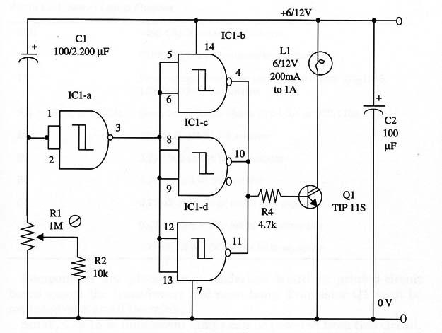
When the power is on, the lamp is powered on, at which time Cl begins to charge through R1 until V1D is reached. Then, the IC 1-a output goes high, and the driver stages formed by ICI-b, c, and (1 have their outputs drop to the low level. Thus, the output transistor is out off, and Ll turns off.
The circuit can be powered from 6 to 12 V supplies. The lamp selection is according this voltage, and the rated current must be in the range of 100 mA to 1 A.
You can replace the lamp by a high power white LED with a 22 to 100 ohm series resistor, according the rated current for the LED.
The circuit can be used in an automatic illumination system and in many other applications. To extend its power capabilities, you can replace the lamp with a 6 or 12 V relay.
A schematic diagram of the Delayed Turn-Off Lamp is shown in Fig. 1.

Transistor Q1 must be mounted on a heatsink. Several types of lamps are suitable for use in this project.
To convert this circuit to a turn-on lamp, switch the position of C1 With the combination of R1/R2.
IC1 - 4093 CMOS integrated circuit
Q1 - TIP120 NPN Darlington power transistor
L1 – 6 or 12 V incandescent lamp (see text)
R1 - 1,000,000 ohm potentiometer
R2 - 10,000 ohm, 1/4 W, 5% resistor
R3 - 4,700 ohm, 1/4 W, 5% resistor
C1 - 100 µF/220 µF, 16 WVDC electrolytic capacitor (see text)
C2 - 100 µF, 16 WVDC electrolytic capacitor


