The project can be powered from four AA cells or a 9 V battery. Current drain depends on the state of the LED.
With the LED off, current drain is only about 1 mA. With the LED on, current drain is between 10 and 30 mA according to the power-supply voltage and R3.
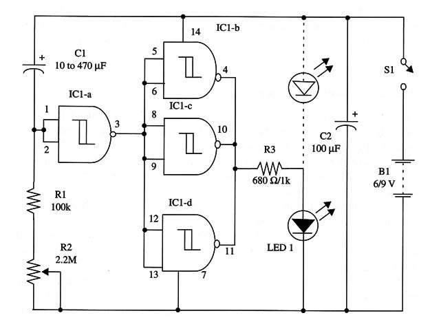
If you want a turn-off action for the LED, wire it as shown by the continuous line in the schematic diagram. If you want a turn-on action, wire the LED as shown by the interrupted line in the schematic diagram.
The circuit works as follows. When S1 is closed, the IC1-a output is low, and Cl begins to charge through R1 and R2 until Vn is reached (pin 2). At the same time, ICl-b, c, and d outputs are high, and the LED is on.
When Vn is reached, the IC1-a output goes high, and this logic level is applied to IC1-b, c, and d inputs. The three gates’ outputs, initially at the high level, pass to the low level, turning off the LED. If the LED is wired to the positive power line, this component, initially off when S1 is closed, turns on after the adjusted time delay.
A schematic diagram of the Simplest Timer is shown in Fig. 1.

The time delay depends on the capacitor C1. With a 470 µF capacitor and a 4.7 M ohm potentiometer, the maximum time delay is about half an hour. Capacitors up to 1,000 µF can be used for longer time delays.
You can also mount your timer on a printed circuit board and house it into a plastic box to provide a portable version.
IC1 - 4093 CMOS integrated circuit
LED1 - Red common LED
S1 - SPST switch
R1- 6 or 9 V, four AA cells or 9 V battery
R1 - 100,000 ohm, 1/4 W, 5% resistor
R2 - 2,200,000 ohm or 4,700,000 ohm potentiometer
R3 - 680 ohm, 1/4 W, 5% resistor (6 V supply), 1,000 ohm2, 1/4 W, 5% resistor (9 V supply)
C1 - 10 µF to 470 µF, 16 WVDC electrolytic capacitor
C2 - 100 µF, 12 WVDC electrolytic capacitor


