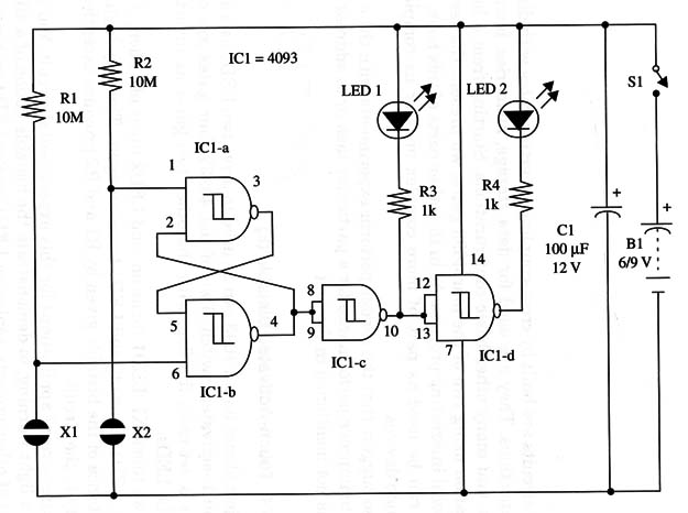
When we touch X1, LED1 turns on, and LED2 turns off. Then, if we touch X2, LED1 turns off, and LED1 turns on again. The very high input resistance of the bistable given by R1 and R2 provides exceptional sensitivity to the circuit.
There are several applications for this experimental circuit. You can use it as a light warning, to demonstrate the bistable action of a 4093, or as part of other projects, replacing LED1 and/or LED2 with powerful transistorized stages driving relays, lamps, or other loads.
The circuit is powered from 6 or 9 volt batteries or power supplies, and current drain is about 20 mA (9 V).
A schematic diagram of the Touch-Activated Bistable is given in Fig.1.

Positions of the polarized components (LEDs, electrolytic capacitor) must be observed.
X1 and X2 are formed by two metal plates placed in close proximity. They must be touched simultaneously by the fingers to activate the circuit.
If you want to drive powerful light sources such as lamps, or more than two LEDs, you can use transistorized output stages. An NPN general purpose transistor such as the 2N2222 can be driven with a 1 to 4.7 k ohm base resistor and drain of about 100 mA in the collector.
To operate, turn on the power supply (81) and then touch X1 or X2 to turn the LEDs on or off.
IC1 - 4093 CMOS integrated circuit
LED1, LED2 - Common red LEDs, Radio Shack 276-1622 or equivalent
S1 - SPST toggle or slide switch
X1, X2 - Touch sensors (see text)
R1, R2 - 10,000,000 ohm, 1/4 W, 5% resistors
R3, R4 - 1,000 ohm, 1/4 W, 5% resistors
C1 - 100 µF, 12 WVDC electrolytic capacitor
B1 - 6 V or 9 V (four AA cells or battery)


