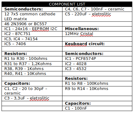
Note: The article is from 2003.
The need to create new media increases every day. One of the most appealing devices that can make use of electronics is the alphanumeric display. Programmed messages run through an LED display placed in an appropriate location. The circuit shown is an alphanumeric display that can present programmed messages of up to 2,000 digits.
A 51 family microcontroller controls the display. It is a Philips 87C751, which has the following main features:
• 8051 compatible instruction set
• 24-pin DIP encapsulation
• 2 Kbytes of program memory
• 64 bytes of RAM
• 19 1/0 pins, programmable as input or output
• Can drive LEDs directly
• Can drain 10 mA current on each pin
• Has a 16-bit timer/counter
• Incorporates two pins for external interrupts
• Includes an I2C serial communications circuit
The keyboard allows the programming of the display in an EEPROM memory with a capacity for 2,000 characters, persisting the information until new programming, even with the power off.
OPERATION
By connecting the keyboard to the device, the display will light up, showing a blinking cursor. To type a character in the position where the cursor is on, press the corresponding key. Each key works for three characters. Press once for the number, twice for the second character, and three times for the third character.
To move the message to the right or to the left to change the characters, press the left or right arrow key.
To review what is programmed, press the B key. To return to the programming mode, press the B key again. The message scrolling speed can be adjusted as follows: press a number from one to nine and hold the return key for approximately 15 seconds.
After programming, go to the end of the message and press the "•" key. This symbol tells the program where the message ends. Finally, turn off the device and disconnect the keyboard. When switching the device on again, the message will appear as programmed.
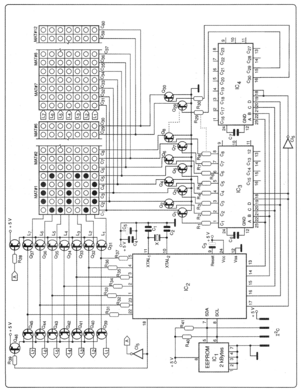
THE CIRCUIT
The display was designed with 7x5 common cathode LED arrays. In total, 12 arrays are used. When connecting the arrays, a display of 7 rows by 60 columns is created. The data is placed in the stacks and is multiplexed in the columns at a sampling rate of approximately 40 Hz. The displays are formed by a matrix circuit that maintains a synchronism between the data placed in the stacks and the switching (multiplexing) of the corresponding column.
The data is placed in port 3 of the microcontroller and amplifier to excite the stacks through transistors Q 31 to Q 46. In port 1, the 74154 decoders that select the corresponding column are connected. Transistors from Q 1 to Q 30 control the electric current to the columns. To obtain the decoders in the multiplexing, 12 arrays were divided into two groups of six, and the data is multiplexed into two groups through Q 38 to Q 46.
Common cathode, small or medium-sized 7x5 LED arrays can be used. The same program can be used for higher consumption matrices, but the amplification step must be redesigned with higher power transistors. The circuit must be powered with 5V x 1A from a stabilized source. The characters are stored in a 2 Kbytes EEPROM with a 120 serial interface. This serial protocol with integrated circuits uses two lines for communication. One line (SDA) handles serial data, and the other (SLC) handles clock pulses.
Each circuit that can communicate over the I2C has an internal address. Thus, when we have to send data to a particular integrated circuit, first we send its address and then the data.
In I2C systems, the device responsible for sending addresses and data is called the master, and it is usually a microcontroller. Devices that receive addresses and data are called slaves and can be EEPROM memories, RAM, input/output ports, counters, LCDs, A/D converters, real-time clocks, etc.
Addresses and data are sent in bytes (8 bits). The clock speed is usually 100 kHz. After each bit is sent, the slave returns an acknowledgement bit to indicate to the master that the byte was received. The communication initiates with a start condition (START) as soon as the address is sent, and if the slave responds, the data is sent. Once the communication with the device is finished, the master sends a stop condition (STOP), and the bus is free for another communication with devices.
The programming keyboard is connected to this bus.
THE PROGRAM
The program starts by initializing variables in the internal RAM where timers and switches are used as well as pointers to the data table. As soon as it is verified that the keyboard is connected and the cursor starts blinking on display, the message scrolling is stopped so that the programming can be carried out. If a key is pressed, decoding takes place so that the corresponding character is stored in the EEPROM.
If the keyboard is not connected, the program looks for the stored characters and times the increment in the EEPROM memory address pointer so that the message moves continuously. When the message ends, the EEPROM pointer is reset, and the message is repeated. Each character is taken from the EEPROM as byte indexes to a data table in the microcontroller's PROM memory for six bytes to show on display.
Every character (letter, number or sign) is formed by 6 bytes in a data table located at the end of the program. If characters non present on the keyboard are required, or if you want to modify existing ones, the table can be reprogrammed. You can even generate logos or pictures. Once the 6 bytes corresponding to a character are displayed, the program will look for the next one in the EEPROM memory and the data table. The program checks when data is placed in the last column to repeat sampling on display. The flowchart shows the program sequence in general.
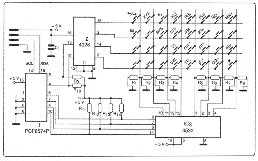
THE KEYBOARD
It is another matrix circuit that uses the multiplexing technique. A decoder using 2 to 4 lines constantly scans the outputs checking for those at the high logic level. Another 8 to 3 lines encoder circuit takes care of detecting which key has been activated. This information passes to the input/output port and is transferred to the microcontroller by the I2C bus. The program decodes this information and persists it in the EEPROM as a character.
For the keyboard connection, cable types like those used in telephony can be used. The cable can be up to 8 meters long. 120 bus can work with this length without problems. Power is available on the same bus.
ASSEMBLY
The circuit can be assembled on a simple proto board (Figure 1). In Figure 2, we have the keyboard circuit, and in Figure 3, the electronic diagram.

SOFTWARE
The program can be obtained through the old website www.eletronicatotal.com.br in the download section.