The described transmitter can be used by radio amateurs or telecommunications services, depending on the chosen frequency. Its high power allows reaches more than 100 km, noting that appropriate antenna and receiver must be used.
The presented valve circuit must be mounted by people who have experience with assembly of high frequencies circuits. The critical components in this case, besides the valves are transformers and coils that must be wound by the assembler itself.
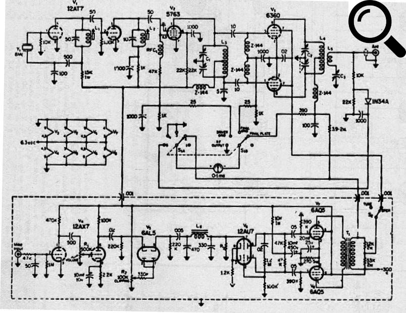
The modulator appears between dashed lines, consisting of an audio power amplifier. The high voltage source of 300 V with the current of 300 mA is not included in the diagram.
The coils have the following characteristics:
L1 1.6 µH
L3 - 0.90 µH
L5, L2 - 0.4 to 0.65 µH
L4 - four turns of wire 14 in the form ½ inch
L5 - 2 turns of wire 14 coupled together with L4
X - 8 MHz crystal
Z144 - 2.5 µH
In figure the diagram of the transmitter.