Features
Power supply voltage: 6 to 12 Vdc
Frequency range: 88 to 108 MHz
Number of transistors: 4
Range: several Miles
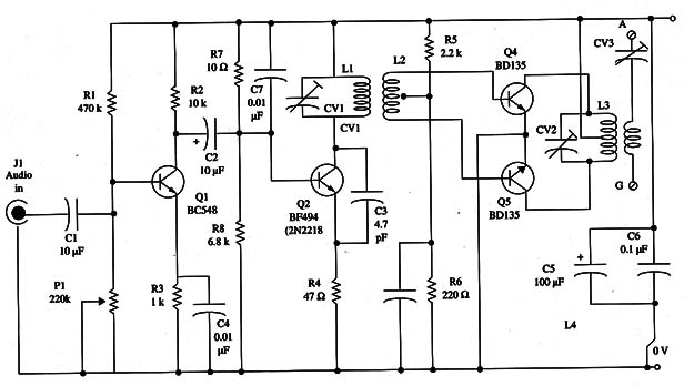
A high-power push-pull output stage using two transistors gives this project a performance range of up to several miles when used with an external antenna.
The output power also depends on the power supply voltage.
The reader can use supplies ranging from 6 to 12 V with this transmitter.
If dry cells are used for the 6 V version, they must be D or C types, as the current drain is high.
The circuit needs three adjustments to be made using three trimmer capacitors.
Procedures for making these adjustments can be found in the descriptions of other projects in this section.
The external modulation can come from various sources such as mixers, a high-impedance microphone, CD players, or others.
A mixer can be used to plug several signals into the transmitter if it is used in an experimental radio station.
The operational frequency is determined by the coils, and the reader has some options as shown below:
50 to 80 MHz
L1 6 turns
L2 4 + 4 turns enlaced with L1
L3 6 + 6 turns
L4 5 turns enlaced with L3
80 to 120 MHz
L1 4 turns
L2 3 + 3 turns enlaced with L1
L3 4 + 4 turns
L4 4 turns enlaced with L3
All the coils are wound around a pencil as reference.
The wire can be the AWG 20 to 24 (enameled or plastic covered).
Figure 1 – Schematic diagram of the transmitter.

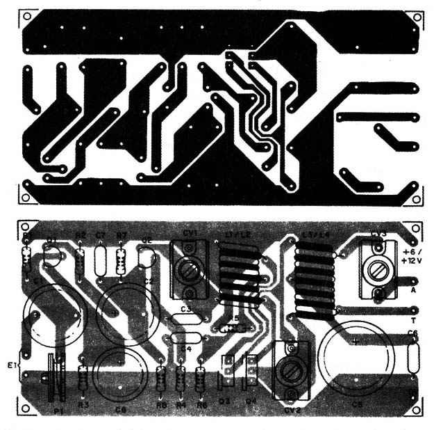
All the components are placed on a printed circuit board as shown in Fig. 2.

Pay special attention to the placement of the coils.
The transistors can be replaced by equivalents.
Q3 and Q4 must be mounted on small heat sinks if the circuit is powered from a 12 V supply.
The recommended trimmers capacitors can be porcelain or plastic types with capacitance ranges from 2-20 to 4-40 pF.
The small capacitors must be ceramic types.
The electrolytic capacitors are rated to voltages up to 16 V or as specified in the parts list.
If an external antenna is used, it must be wired to the circuit using a coaxial cable.
The trimmer potentiometer is used to adjust the modulation according to the audio signal source.
Semiconductors
Q1 - BC548 or equivalent general-purpose NPN silicon transistor
Q2 - BF494 or equivalent high-frequency (RF) NPN silicon transistor
Q3, Q4 - BD135, BD137, or BD139 medium-power NPN silicon transistor
Resistors (1/8 W, 5%)
R1 - 470,000 Ω - yellow, Violet, yellow
R2 - 10,000 Ω - brown, black, orange
R3 - 1,000 Ω - brown, black, red
R4 - 47 Ω - yellow, violet, black
R5 - 2,200 Ω - red, red, red
R6 - 220 Ω -red, red, brown
R7 - 10,000 Ω -brown, black, orange
R8 - 6,800 Ω -blue, gray, red
P1 - 220,000 Ω - trimmer potentiometer
Capacitors
C1, C2 - 10 µF/ 16 WVDC electrolytic
C3 - 4.7 pF ceramic
C4 - 0.01 µF ceramic or metal film
C5 100 µF/ 16 WVDC electrolytic
C6 - 0.1 µF ceramic
C7 - 0.01 µF ceramic
CV1, CV2, CV3 trimmers (see text)
Additional Parts and Materials
L1, L2, L3, L4 coils (see text)
Printed circuit board, plastic box, input jack, power supply, etc.


