The simplest Way to use a transmitter to send information using radio signals is by continuous Wave (CW). The transmitter is a simple high-frequency oscillator plugged into an antenna as shown in Fig. 1.
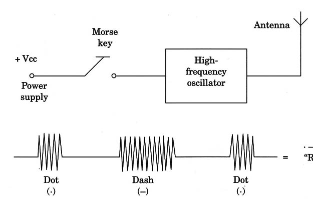
In this kind of transmission technique, the signals produced by a circuit are switched on and off by a key.
A short signal burst represents a dot (-), and a long signal burst is a dash (-). Combining dots and dashes in Morse code, we can represent all alphabetic and graphic symbols and numbers. (See the site for the Morse Code)
For instance, a short burst followed by a long burst [Coded as a dot-dash (- -)] means the letter A.
Experienced operators can send complete, long messages Very quickly.
And, of course, it is necessary to have a good ear to decode the received signals.
Today, this kind of transmission is used only by a feW operators. (Radio amateurs and radío operators must know Morse code, as it can be useful in emergency situations).
You can tune in this kind of transmission with your shortwave receiver (in the 7 to 14 MHZ range, for instance) as long and short or burst of signals without any modulation.
It is important to remínd the reader that a CW transmitter is so simple that, in an emergency situation, even an antique radio receíver for the MW or SW band, or a television set, can be converted to send telegraphic signals.
Figure 2 shows an audio output stage as used in many antique radios and TVs using a pentode tube.
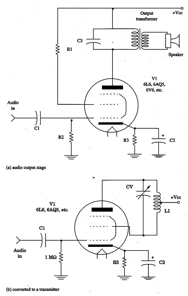
By replacing some components wired to this tube, as shown in the same figure, we can change it into a CW transmitter for emergency situations.
A transmitter like this can send signals distances of hundreds or thousands of miles under favorable propagation conditions.
To send signals in the frequency range between 3 and 7 MHz (40 and 80 meter radio amateur band), the coil is formed by 15 + 15 turns of enameled AWG 28 wire wound on a PVC or wooden tube with a diameter of 1 inch.
If the tube is a 6V6 or a 6L6, the power can be as high as 5 W and, with an appropriate antenna, the signals can reach distances up to a thousand miles. Less power is obtained from tubes such as the 6AQ5 or 50C5.
Using the transmitter is very simple: using a key, you merely turn on and off the high voltage that is applied to the stage.
Before the vacuum tube was invented, transmitters were much simpler. The transmitters used at that time were based on the production of electric sparks, as shown in Fig. 3.
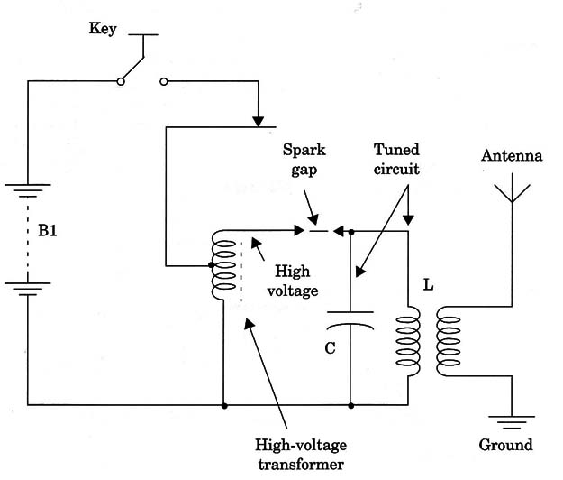
A typical spark transmitter was formed using a high-voltage coil to produce a high voltage between two points.
A spark was produced in the gap between the points, generatinga high-frequency signal.
A resonant LC circuit was placed in series with the spark generator to determine the frequency of the signal. Marconi sent radio waves across the Atlantic Ocean using a transmitter like this.
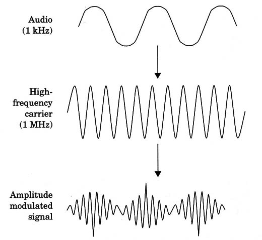
With the invention of tubes, modulation techniques advanced. Injecting an audio signal produced by a low-frequency oscillator into a high-frequency carrier, it became possible to change the signal’s amplitude.
This kind of modulation results in a tone-modulated telegraphic system, as shown in Fig. 4.
We can also consider using the injection of a signal coming from a microphone to alter the characteristics of a high-frequency carrier.
There are two ways to change the carrier characteristics and therefore two ways to transmit sounds using radio waves.
Amplitude Modulation.
Using amplitude modulation (AM), we can change the amplitude or the amount of power of the radio signal using the low-frequency or audio signal.
For instance, if we have a 1,000 Hz signal to be transmitted, this signal changes the amplitude of the radio signals 1,000 times per second.
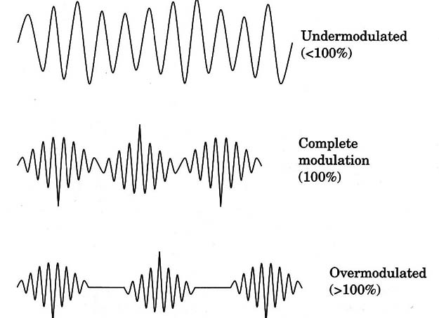
To be more efficient, the high-frequency signal in a radio transmission using amplitude modulation must be 100% modulated.
This means that the amplitude of the carrier can vary in a range of 0 to 100% of its value according to the audio signal.
If the changes are less than this value, we have a condition called undermodulation, and the efficiency of the transmitter is low. If we create changes above 100%, as shown in Fig. 5, an overmodulation occurs, causing problems relating to interference, distortion, and undesirable signals produced by the equipment.
Amplitude modulation is used in broadcasting stations operating in the MW and SW ranges, by radio amateurs, and in many other telecommunication services.
It has some disadvantages, one of which is sensitivity to noise and interference.
Noise and interference signals can appear at the moment when the radio signal is in the lowest amplitude point in each cycle.
That means that they prevail and appear as noise reproduced by the receiver’s loudspeaker.
Frequency Modulation.
Another kind of modulation is called frequency modulation (FM). To produce an FM signal, we must change the frequency of a carrier (not the amplitude) according to the amplitude and frequency of an audio signal as suggested by Fig. 6.
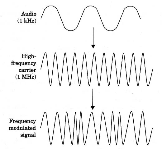
For instance, if we use a 1 kHz audio signal to modulate a 100 MHz signal, the 100 MHZ will change its frequency between two vaues (for instance 99.5 and 100.5 MHz) 1,000 times per second, according to the audio signal.
The principal advantage of this kind of modulation is that we have no low amplitude points to be affected by noise and interference.
This means that FM is less sensitive to noise than AM.
Other types of modulation like PWM, Phase Modulation, etc. can be found in articles in the site.


