Features
Three-stage high-gain audio amplifier
Frequency range: 88 to 108 MHZ
Power supply voltage: 6 VDC (four AA cells)
Range: up to 200 ft
Number of transistors: 4
Current drain: 5 mA (typical)
This project adds an ultra-high-gain audio amplifier to an FM transmitter. As a result, very weak sounds picked up by an electret microphone can be transmitted and heard in a remote receiver.
The high-sensitivity characteristic and the high stability due to a zener regulation stage make this transmitter ideal for secret missions. Hidden in a room, it can send any conversation, even a murmur, to a receiver that is plugged into a tape recorder or an earphone.
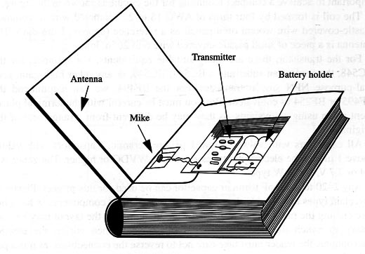
Our suggestion is install the circuit inside a hollowed-out book (fig 1) and place it on a shelf near the conversations to be overheard. In this way, it will not be noticed.

But you can hide the circuit in other objects such as flower pots, conceal it behind tables, place it among other books, or hide it anywhere your imagination prescribes. The low current drain provides a battery life of several weeks.
How It Works
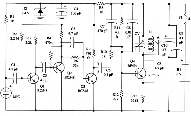
The audio amplifier is formed by three transistorized stages. The first transistor picks up the signal from an electret microphone by C1. The transistor wired in the common emitter configuration is biased by R2. The signal amplilied by Q1 is applied to the second stage by C3. The second stage is formed by Q2, which is biased by R4.
From this transistor collector, the signal is applied to the third stage via C5 R6, placed in parallel with this capacitor, biases the third transistor’s base.
All three transistors are powered from a regulated power supply. The voltage is fixed by the zener diode at 2.4 V. Resistor R8 reduces the current How through the zener diode to a compatible level. Filtering of the supply to this stage is provided by C4.
This regulation stage is important, as it provides stability to the circuit even when the cell’s voltage falls during use.
The high-frequency stage is formed by Q4 and the components placed around it. L1 and CV determine the oscillation frequency. CV must be adjusted to a free point in the FM band between 88 and 108 MHz.
To avoid saturating the circuit, the modulation signal is attenuated by R10, R11 and R12 bias the oscillator transistor, and C8 provides the necessary feedback to keep this circuit running.
Note that the antenna can be connected to any point between the collector and a tap in the coil. The reader, through experimentation, must determine the best point to connect the antenna. C9 and C10 are used to decouple the power supply.
Assembly
A complete diagram of the spyphone is shown in Fig. 2.

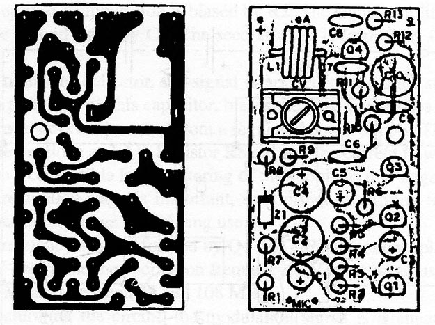
All the components, except the battery holder and the electret microphone, are mounted on a printed circuit board as shown in Fig. 3.

Notice that the resistors are mounted in a vertical position, and the electrolytic capacitors are parallel-terminal types. This is important to achieve a compact mounting for the circuit as shown in the figure.
The coil is formed by four turns of AWG 18 to 22 enameled wire or common plastic-covered wire wound on a pencil as a reference (approx. 1 cm dia.). The antenna is a piece of solid plastic-covered wire 6 to 20 in. long.
For the transistor, there are many suitable equivalents. For instance, for the BC548, the reader can substitute a BC547, BC549, or any other high-gain, general-purpose NPN silicon transistor.
For the BF494, we can recommend the BF495 or BF254 as equivalent. But you must be careful with the terminal placement when using equivalents, as they may be different from arrangement of the originals.
All capacitors with values below 1 µF are ceramic. Capacitors with values above 1 µF can be electrolytic types rated to 6 WVDC or higher. The zener is a 2.4 or 2.7 V, 400 mW type.
Any 2-20 to 4-40 pF trimmer capacitor can be used for this project. Plastic or porcelain types are suitable. It is important to have these components in hand before etching the printed circuit board, as modifications in the layout may be necessary to match the device's terminal placement.
When wiring the electret microphone, the reader must take care not to reverse the connections, as it is a polarized component.
Adjustments and Use
Place an FM receiver near the spyphone. If possible, use a receiver with an earphone. If you use a loudspeaker instead of an earphone, the high-gain audio circuit can produce acoustic feedback, making adjustments difficult.
Turn the transmitter power on and tune the receiver to a free point in the FM band. Adjust CV until you pick up the strongest signal. When tuned, the ambient sounds will be clearly audible.
When using the transmitter, avoid placing it near metal objects. If it is installed inside a hollow book, the unit can be placed as shown in Fig. 1.
When positioning the book to pick up conversations, you will get the best results With the antenna placed in a vertical position. Avoid placing the transmitter on a table, as moving objects in contact with the table can generate noise that will interfere with your reception.
The receiver can be plugged into the input of any tape recorder.
Semiconductors
Q1, Q2, Q3 – BC548 or equivalent general-purpose NPN silicon transistor
Q4 - BF494 or BF495 high-frequency N PN silicon transistor
Z1 - 2V4 (2.4 V) x 400 mW zener diode
Resistors (1/8W, 5%)
R1 - 2,200,000 ohm - red, red, green
R3 - 2,200 ohm - red, red, red
R4 -47 0,000 ohm - yellow, violet, yellow
R6 - 56,000 ohm - green, blue, orange
R7 - 560 ohm - green, blue, brown
R9 470 ohm - yellow, violet, brown
R10 - 100,000 ohm - brown, black, yellow
R11 - 47,000 ohm - yellow, violet, orange
R11 - 27,000 ohm - red, Violet, orange
R13 - 56 ohm - green, blue, black
Capacitors
C1, C3, C5 - 4,7 µF/6 WVDC electrolytic
C2, C4 - 100 µF/6 WVDC electrolytic
C6, C9 - 0.1 µF ceramic
C7 - 470 pF ceramic
C8 - 4.7 pF ceramic
C10 - 47 µF/6 WVDC electrolytic
CV trimmer (see text)
Additional Parts and Materials
L1 - coil (see text)
MIC - electret microphone - two terminals
S1 - SPST toggle or slide, miniature switch
B1 - 6 V, four AA cells
Printed circuit board, battery holder, plastic box or hollow book, solder, wires, etc.


