Note: this project is part of the book Science Fair and Technology Education Projects by the author.
Although it operates according to the same principles of earlier transmitters without any control for tuning, as the ones from the end of the XIX century, it is not recommended to connect it to external antennas. It serves only for short range demonstrations since it irradiates much more interference than signals.
Producing a radio signal does not need a tuning circuit with coils and capacitors as it is usually found in modern equipment. In fact, the first radio transmitters built in the earlier times of radio communications does not use any coil or capacitor, as we can see in the first experiments of Marconi, Tesla, Landel de Moura, and other.
Of course, the presence of a resonant circuit, formed by coils and capacitors is very important to guarantee the generation of a precise frequency signal.
Otherwise, this unique frequency we will have is nothing but noise spreading by the radio spectrum, producing an undesirable effect of interference in any receiver. The circuit described here, operating in a fixed frequency and without any coil, can be classified as an experimental transmitter.
Since the signal does not have a determined frequency, any antenna could be used, limiting the range to a few meters depending on the sensitivity of the receiver used in the experiment.
The transmitted signal can be picked up in practically any type of radio. Models that tune from AM 550 kHz to short wave and FM up to 100 MHz will tune the transmitter, if placed near the experimental transmitter. But, considering the circuit cannot be tuned, it is impossible to modulate the signals and a microphone can’t be used.
So, the transmitter will send only telegraph signals in a mode named CW (Continuous Wave) where the wave is directly controlled by the key. It is a transmitter like the first ones experimented by Marconi.
How it Works
An integrated circuit 4093 CMOS (Four NAND Schmitt Gates) is connected as a high frequency oscillator. The basic generated frequency is determined by C1 and adjusted by P1. Although this circuit produces signals in the range between 100 kHz and 2 MHz, the transmitter will not actually operate in this band.
What happens is that the generated signal is a harmonics rich square wave that spread its frequency to many MHz above, reaching the FM band. These harmonics can be tuned in any part of the radio spectrum between 500 kHz and 100 MHz.
Figure 1 shows how the signals produced by the transmitter are distributed along the radio spectrum.
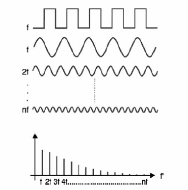
This means that, if we ‘tune’ the transmitter to 100 kHz, signals spreading along the spectrum in intervals of 100 kHz will be generated. The signal produced by one gate connected as oscillator is applied to the input of the other gates that act as amplifiers.
The final output is then applied to a small piece of wire operating as an antenna. With this configuration, the range will be about 2 or 3 meters. This range can be increased if we add a low power transistor as amplifier.
The circuit can be powered by power sources in the range between 3 V and 12 V and the current drain is very low, extending the operating time if cells are used. The telegraphic key is placed in series with the power supply.
Morse coded messages can be transmitted to a receiver placed in a neighbor room. You can use the transmitter to practice coding.
Building
Figure 2 shows the complete diagram for the transmitter.
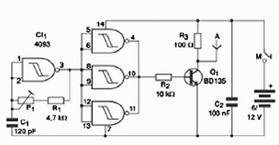
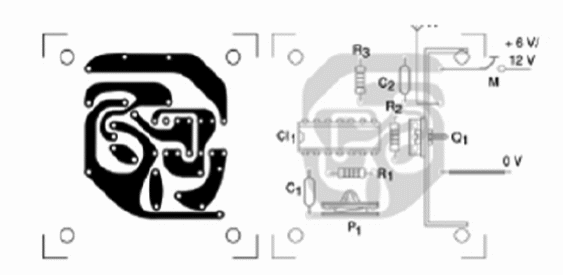
The components placement on a printed circuit board (PCB) is given in figure 3.
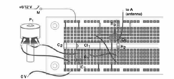
A DIL (Dual in Line) socket is recommended for the IC. You can also assemble the project using a proto-board, as shown in figure 4.
The resistors are all 1/8 or 1/4 W and the capacitors are ceramic or polyester types. C1 is not critical, and its values can range from 120 pF to 330 pF. For C2, the values can range from 100 nF to 470 nF.
The power supply consists in common cells with a holder or a 9 V battery with connectors. You can also use an AC/DC converter rated to 3 to 9 V x 200 mA or more. The telegraphic key can be a home made unit as described in other projects of this book.
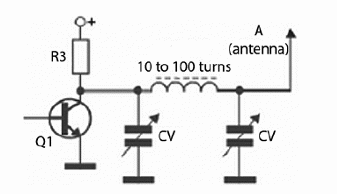
Figure 5 shows how to add a tuned filter to the transmitter to increase its performance.
Testing and Using
Place the transmitter near an AM or FM radio tuned to a random point of the dial. Press the telegraphic key and adjust P1 to pick up the strongest signal. Take the receiver far from the transmitter to test the range.
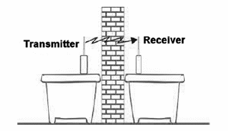
Once the transmitter shows it is working well, you can start with your transmissions. An idea to make your transmissions more interesting is placing the transmitter and the receiver in different rooms, as show in figure 6.
To memorize the Morse code, start transmitting only isolated letters and symbols. Find a colleague to transmit or receive. In a second step, you can transmit and receive isolated words. And finally, when you fell you are able to receive any message, transmit and receive complete phrases.
Competition and challenges:
1. Give a prize for the highest range project
2. Propose a challenge to the pupils: add a microphone to transmit the voice.
Semiconductors:
CI-1—4093—CMOS Integrated circuit
Q1—BD135—Medium power NPN silicon transistor
Resistors (1/8 W, 5%):
R1—4.7 k ohm—yellow, violet, red
R2—10 k ohm—brown, black, orange
R3—100 ohm—brown, black, brown
P1—47 k ohm—lin or log potentiometer
Capacitors:
C1—100 pF—ceramic
C2—100 nF—ceramic
Other:
M—Telegraphic key
A—Antenna—see previous text
Printed circuit board or proto-board, cell holder, socket for the integrated circuit, box to install the circuit, wires, solder, etc.


