

The tone systems, as we have seen in previous articles, detect an audio signal sent by the transmitter and trigger a corresponding command circuit.
The critical point of this type of design is the filter that must have sensitivity to recognize the weakest audio signals and selectivity so as not to confuse them with the adjacent channels.
The design that follows is a filter that recognizes a tone and therefore can be turned on at the output of any receiver for the formation of a multichannel remote control system.
There will be as many filters as the reader wants, depending on the number of channels in your system, with a maximum of 10 units.
In figure 1 we have a basic idea of ??applicationa in blocks where we can with 5 filters have a control system for a car.
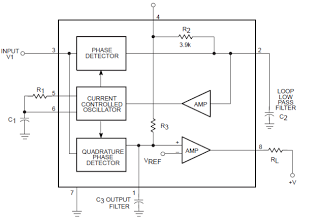
Two channels are used to drive the motor and reverse its rotation. Two other channels are used to turn right and left. Finally the fifth channel can be used to control some special features like headlights, horn, automatic opening of a door, etc.
The basis of the project is the 567 integrated circuit consisting of a PLL and having
the basic configuration shown in figure 2.
By adjusting the P1 trimpot of this circuit, and depending on the value of the capacitor, we can make it recognize frequencies between 200 and 20 000 Hz approximately, with excellent selectivity and sensitivity, that allows its connection directly in the audio outputs of any of the receivers that we describe.
The output of the 567 is of sufficient intensity to directly drive a transistor with a relay, which greatly facilitates the design and allows its assembly in modules.
Another important feature for design is that this integrated operates satisfactorily with a voltage of 6 V and has a low consumption.
THE PROJECT
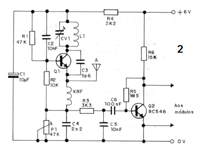
We begin by giving the schematic diagram of the receiver module that can operate at any frequency between 27 and 100 MHz, depending on the coil used and eventually with the replacement of capacitor C3. For frequencies up to 40 MHz this capacitor shall be 47 pF, for frequencies between 40 and 60 MHz shall be 22 pF and above 60 MHz 10 or 4.7 pF.
For the FM range the L1 coil will have 4 turns of wire 20 or 22 in 1
cm in diameter without core,
The printed circuit board for the receiver module is shown in figure 3.
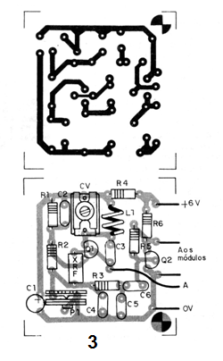
The resistors are 1/8 watt or larger and the capacitors are all ceramic except for C1 which is electrolytic for 6 V and C6 which can also be made of polyester.
Transistor Q1 can be replaced by BF495 and BC547.
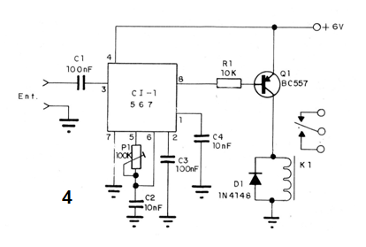
The module of a filter with the 567 has the schematic diagram shown in figure 4.
The printed circuit board corresponding to this filter is shown in figure 5.
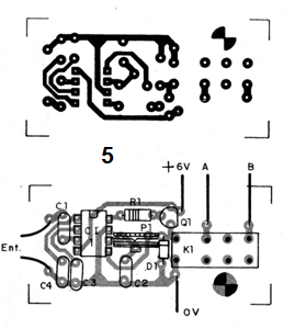
The reader can draw the same repeat pattern on a single plate and thus obtain a multi-channel filter.
The resistors are 1/8 watt and the capacitors can either be ceramic, metallized polyester or the like. The relay is 6V and the power to each module must not exceed 10V.
The indicated relay can be mounted in a 16-pin DIL socket and has a contact capacity of 2 amps.
P1 adjusts the frequency that the filter accepts. The procedure for this adjustment is given below.
The transistor also supports equivalents.
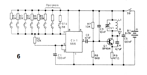
The transmitter is shown in figure 6.
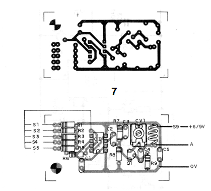
In figure 7 we have the printed circuit board of the transmitter that has a range of up to 100 meters with 6 V supply in preaching the described receiver.
The number of push buttons in the modulation step of this transmitter depends on the number of channels desired, see figure 7.
The transmitter coil must be the same as that of the receiver, so that they both operate at the same frequency, which will be adjusted in the corresponding trimmers.
The resistors should all be 1/8 watt and the capacitors must be ceramic type disk.
The transmitter can be supplied with batteries or batteries. The telescopic antenna of both the receiver and the transmitter must be at least 60 cm for better performance and should not exceed 1.20 meters in order to avoid instability.
TEST AND USE
Initially connect the output of the receiver to an audio amplifier according to the procedure we have explained in previous projects. Then adjust the trimmer of the receiver and the transmitter for signal reception. Adjust the trimpot of the receiver so that it has greater sensitivity without operating instabilities.
Having proven the operation of the transmitting step and the receiving step,
we checked the filters.
Then press the button of the first transmitter channel and adjust the receiver's corresponding trimpot until the relay closes its contacts. Be careful not to calibrate the filter in harmonics.
We then do the same operation with the other channels.
If in some channel we have to drive two relays instead of one, we must change the frequency of the transmitter in the audio sector by changing the value of the resistor that is associated with the pushbutton of the channel that caused problems. Experiment until all channels work, without interference from one another.
A) TRANSMITTER
SEMICONDUCTORS
Cl-1 - 555 - integrated circuit
Q1 - BF494 or 2N2218 - RF transistor
RESISTORS
R1, R6 and R7 - 10 k ohm (brown, black, orange)
R2 - 12 k ohm (brown, red, orange)
R3 - 15 k ohm (brown, green, orange)
R4 - 1k ohm (brown, gray, orange)
R5 - 22k ohm (red, red, orange)
R8 - 6k8 ohm (blue, gray, red)
R9 - 47 ohm (yellow, violet, black)
CAPACITORS
C1 to C5-100 nF (ceramic or polyester)
C2-47 nF (ceramic)
C3-10 nF (ceramic)
C4 - 4.7 pF (ceramic)
VARIOUS
L1 - Coil - see text
B1 - 6 or 9 V - batteries or battery
S9 - Single switch
S1, etc. - pressure switches
Printed circuit board, box, battery holder or clip for battery, antenna, wires, solder, socket for the integrated, etc.
B) RECEIVER
SEMICONDUCTORS
Q1 - BF494 or BF495 - RF transistor
Q2 - BC548 or equivalent - general purpose NPN transistor
RESISTORS
P1 - 47 k (trimpot)
R1 - 47 k ohm (yellow, violet, orange)
R2 - 10 k ohm (brown, black, orange)
R3 - 3k3 ohm (orange, orange, red)
R4 - 2k2 ohm (red, red, red)
R5 - 1M5 ohm (brown, green, green)
R6 - 15 k ohm (brown, green, orange)
CAPACITORS
CV1 - 3-30 pF (trimmer)
C1 - 10 uF (electrolytic)
C2-10 nF (ceramic)
C3-5p6 (ceramic)
C4-2n2 (ceramic)
CS-10 nF (polyester or ceramic)
C6-100 nF (polyester or ceramic)
VARIOUS
XRF - 100 uH - microchoke
L1 - coil - see text
A - antenna - see text
Printed circuit board, wires, solder, etc.
C) FILTER (One unit)
SEMICONDUCTORS
CI-1 - 567 - PLL integrated circuit
Q1 - BC548 - NPN general purpose transistor
DI-1N4148 - silicon diode
RESISTORS
P1 - 100 k - trimpot
R1 - 10 k ohms (brown, black, orange)
CAPACITORS
C1 to C3-100 nF (ceramic or polyester)
C2-10nF at 47nF (ceramic or polyester)
VARIOUS
K1 - 6 V relay
Printed circuit board, integrated socket, relay socket, wires, solder, etc.


