The 3-transistor radio we describe uses common components, many of which can be availed from other out-of-use AM radios. The circuit is powered by 4 batteries and with a small antenna and good ground connection can pick up several local stations. Note the connection of the inverted batteries, as we use PNP transistors in this circuit.
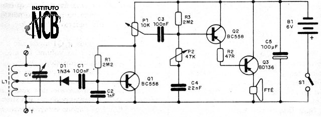
The operation is simple to understand. It is a simple direct detection and amplification receiver. The signals selected by the tuning circuit are detected by D1, extracting the modulation that receives a first amplification by Q1.
Passing through P1, which is the volume control, the signal is taken to a stage with good gain Darlington that excites the small speaker. The circuit has a tone control via P2.
Assembly
In figure 1 we have the complete circuit of the receiver.

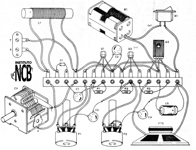
A recommended assembly is a contact array or printed circuit board, but there is the simplified terminal strip option, shown in Figure 2.

The coil consists of 30 + 70 turns of enamelled wire 28 or 30 on a ferrite rod and the variable capacitor CV can be harnessed from an out-of-use AM radio.
On assembly, observe the positions of the transistors and the polarity of the diode and the electrolytic capacitor, as well as the battery holder. The resistors are 1/8 W with any tolerance and the 4 or 8 ohm speaker with 5 to 10 cm.
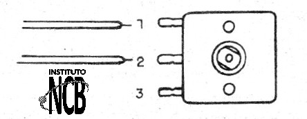
In figure 3 we show where the connection of a variable of small radic plastic must be made.

To test, simply turn on the radio and try to pick up a station by setting P1 and CV.
Q1, Q2 - BC558 - general purpose NPN transistors
Q3 - BD136 - medium power PNP transistor
D1 - 1N34 - germanium diode
FTE - 4 or 8 ohm - small speaker
S1 – On/Off switch
B1 - 6 V - 4 small batteries
L1 - Coil - see text
CV - variable capacitor
P1 -10 k ohm - potentiometer
P2 - 47 k ohm - potentiometer
R1, R3 - 2M2 ohm - resistors - red, red, green
R2 - 47ohm - resistor - yellow, violet, black
C1, C2 - 100 nF Ceramic capacitors
C3 - 100 uF - electrolytic capacitor for 6 V or more
Several:
Terminal strip, battery holder, wires, solder, etc.