Buzzers found in various types of devices consist of a ceramic transducer that can operate both reproducing sounds, and conversely, as a microphone. The sound vibrations it picks up deform the material that then produces a voltage that can be used by an electronic circuit.
In our case, the buzzer acts like a microphone, modulating a small transmitter of only one transistor that operates in the FM range.
Assembly
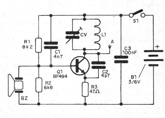
In figure 1 we have the complete diagram of the transmitter.

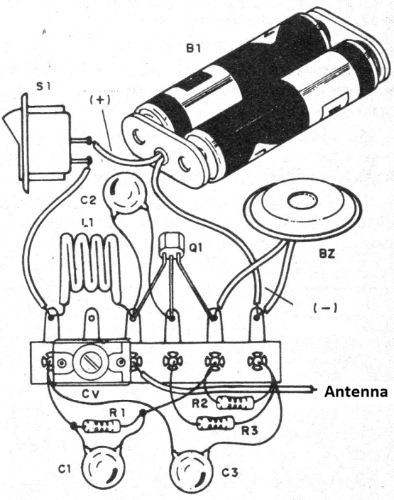
In figure 2 we have a suggestion of assembly using a terminal strip.

The coil is formed by 4 coils of ordinary strand 22 rigid or enameled enamel 24 to 28, with a diameter of 1 cm without core. The trimmer can be either the old porcelain-based type harnessed from old out-of-use appliances like modern plastic rounds, with maximum values of 10 to 30 pF.
The capacitors must be ceramic and the antenna can be either a 10 to 30 cm piece of hard wire or a telescopic antenna. The set can be installed in a small plastic box, where there are also two batteries that will power it.
Test and Use
Simply turn on the unit and adjust the trimmer to pick up your signal on an FM receiver tuned to a free frequency, placed nearby. Look for the strongest signal and step back to check its range.
When operating, always keep the antenna in an upright position away from your hand or any object.
Q1 - BF494 - RF transistor
BZ - Ceramic transducer (buzzer)
R1 - 8k2 x 1/8 W- resistor - red, gray, red
R2 - 6k8 x 1/8 W - resistor - blue, gray, red
R3 - 47 ohm x 1/8 W - resistor - yellow, violet, black
C1 - 4n7 - ceramic capacitor
CV- trimmer - see text
C2 - 47 pF - ceramic capacitor
C3 - 100 nF - ceramic capacitor
S1 – On/Off switch
B1 - 2 AA or AAA batteries
Several:
Terminal block, 2-cell holder, mounting box, wires, solder, etc.


