Obs. This article was originally written in Portuguese to a Brazilian magazine and translated into English to be included in one of my books.
Features
Powered from the ac line
High power, with the ability to jam signal sources over a 300 ft radius
Wide frequency band operation, canceling signals in the range between 60 and 120 MHz
Built with common parts
Needs no adjustment
The best away to cancel the signal of a spy transmitter hidden in a room is to use a strong high-frequency signal to cover the signal produced by the undesirable transmitter (i.e., the “bug”). The circuit described here has just this function: it is a high-power noise transmitter that covers the FM and VHF bands and produces a strong hum in any FM receiver located within a distance of approximately 150 ft.
If the spy’s receiver is placed within range, it will not be able to tune in the signal of the bug, which will be overpowered by the noise transmitter.
This circuit is designed to cover transmissions in the FM and VHF band, but the reader can make changes for operation in other ranges. An interesting modification recommended for this circuit is replacing the high-frequency circuit with a 800 to 900 MHz oscillator.
This is the cellular telephone frequency range. If you turn on the circuit in your building, no one will be able to use a cell phone to call out or receive messages. This allows you to use the circuit in a conference room or theater to block all cellular telephone calls.
Note: The reader is advised to understand and obey all laws applicable to interference in telecommunication services. This device may be illegal in your country or area.
How It Works
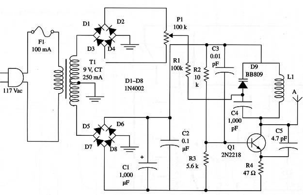
The circuit has two stages. One of them is formed by a high-frequency oscillator that runs in the VHF band. This circuit uses a 2N2218 transistor. The frequency is determined by L1 and the capacitance provided by the varicap diode.
The second stage is the modulation circuit, which acts on the varicap, thereby changing the frequency produced by the oscillator circuit within a broad band.
This stage picks up the 60 Hz power line signal and passes it through a diode bridge, producing a 120 Hz dc pulsed voltage.
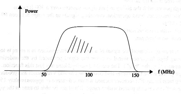
Through P1, this voltage is applied to the varicap diode, modulating the signal. In this way, the high-frequency signal changes its frequency spread within the FM band at a rate of 120 times per second as shown in Fig. 1.

When any receiver that is located near the transmitter is tuned to any point to the FM band, the noise signal will be received at this point 120 times per second, producing a strong 120 Hz hum.
Because the circuit is just intended to produce noise, it does not require any special layout.
Assembly
Figure 2 is a schematic diagram of the noise transmitter.

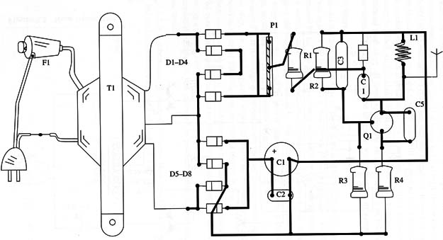
The components are installed on a printed circuit board as shown in Fig. 3.

The transformer consists of a 117 Vac primary winding and any 7.5 to 9 V CT secondary, with currents rated to 250 to 500 mA. The diodes are all 1N4002 or equivalents except D9. D9 is any common varicap such as the BB 809 or equivalent.
As explained in other projects that use varicaps, this component can be found in the tuning circuits of old touch-key TV sets and FM radios that are tuned by potentiometers.
Coil L1 is formed by three to five turns of AWG 18 to 22 enameled or plastic-covered rigid wire on a 1 cm dia. coreless form. You can use a pencil as the reference for winding this coil.
The antenna is a piece of rigid plastic-covered wire 20 to 40 in. long, or a common telescoping antenna.
All of the capacitors must be ceramic types except C1. C1 is an electrolytic capacitor rated to 16 V or more. The circuit can be easily installed in a plastic box.
Testing and Adjusting the Circuit
At a distance of 3 to 9 ft away from the transmitter, place an FM receiver tuned to a free point in the FM band or to any local radio station. Turning on the transmitter (by plugging it to the ac power line), open P1 until a strong hum is produced by the receiver. This is the only necessary adjustment. The transmitter is ready for use.
How to Use
Place the transmitter in any location where you suspect a spy transmitter may exist. The signal will cancel out the spy signal if it is within the operational range. (Of course, your friends also will not be able to tune to their favorite programs in the FM band. This suggests an interesting application for the device if someone in the office likes to listen to awful music programs.
Semiconductors
Q1 - 2N2218 or equivalent high-frequency NPN silicon transistor
D1- D8 - 1N4002 or equivalent silicon rectifier diodes
D9 - BB809 or equivalent variable capacitance diodes (see text)
Resistors (1/8 W, 5%)
R1 - 100,000 ohm - brown, black, yellow
R2 - 10,000 ohm - brown, black, orange
R3 - 5,600 ohm - green, blue, red
R4 - 47 ohm X 1 W- yellow, Violet, black
P1 - 100,000 ohm -trimmer potentiometer
Capacitors
C1- -l 1,000 µF/ 16 WVDC electrolytic
C2 - 0.1 µF ceramic
C3 - 0.01 µF ceramic
C4 - 1,000 pF ceramic
C5 - 4.7 pF ceramic
Additional Parts and Materials
F1 - 200 mA fuse
T1 - transformer, 117 Vac primary Winding, 7.5 to 9 V X 150 mA secondary (see text)
L1 - coil (see text)
A - antenna (see text)
Printed circuit board, plastic box, power cord, fuse holder, Wires, solder, etc.


