Obs. This project was published in a Brazilian magazine and translçated into English to be part of one of my books.
Features
Power supply voltage: 12 V (battery or power supply)
Frequency range: 88 to 108 MHz
Range: more than half a mile
Microphone: low impedance
High-power FM transmitters are very popular among many readers, although regulatory restrictions on their operation limit their practical use. However, a high-power transmitter such as described here can be used on farms, campsites, and other large properties located far away from cities where its operation might interfere with TV and other telecommunication equipment.
The reader who wants a powerful transmitter for experiments or practical applications (within limits) can build this interesting simple circuit using only one transistor.
The original version uses a 2N2218 transistor to achieve a broadcast range of up to a mile, but it is also possible use a BD135 transistor. Although originally designed for audio applications, this component can oscillate in the FM range to achieve the same performance.
Figure 1 shows how the circuit can be installed into a small box to create a portable version.
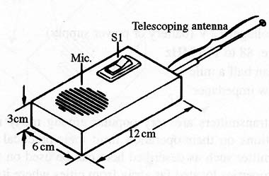
This circuit uses a rechargeable 12 V nicad battery or, if the reader prefers, 6 to 8 AA alkaline cells. Of course, the life span of AA cells is not as long that of the N ICAD battery.
How It Works
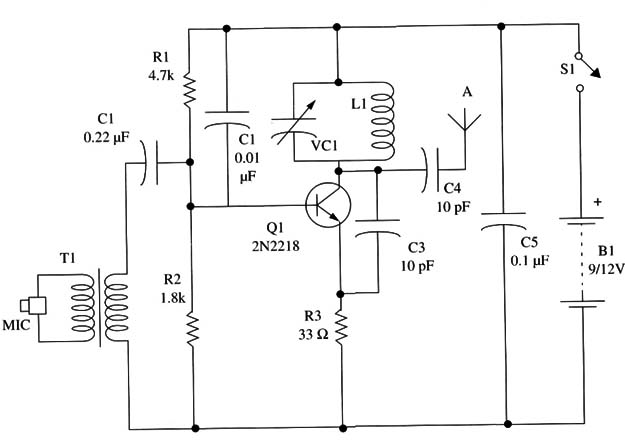
The high-frequency oscillator runs at 88 to 108 MHz, putting the signal at a free point in the FM range. This oscillator is of the same basic configuration using one transistor 2N221 8 as shown in other projects in this site.
The signal frequency is determined by the resonant circuit formed by L1 and the trimmer capacitor CV. The trimmer must be adjusted to tune the circuit to a free point in the FM band. The high-frequency signal produced by this oscillator is applied to the antenna by C4.
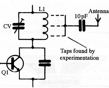
Once again, we recommend that the reader avoid instabilities that may result from wiring the antenna directly to the transistor. You should connect it to an appropriate tap in the coil. By matching the antenna impedance with the circuit impedance, it is possible to get better performance, i.e., avoiding instability and increasing the output power.
Figure 2 shows how the antenna can be connected to the output stage.
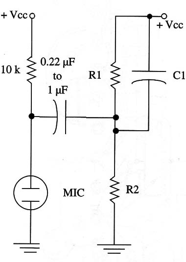
The modulation comes from an electret microphone, as in previously described projects, or from a small loudspeaker. Figure 3 shows how an electret microphone can be wired to this transmitter.
Finally, it is possible to wire the output of a CD player or tape deck into this circuit to broadcast music. Therefore, the project can be used as an experimental radio station.
Assembly
Figure 4 shows the Complete schematic diagram of the transmitter.
Because the Circuit is not Critical, if the reader keeps the terminals and wires short, a terminal strip can be used as the chassis as shown in Fig. 5.
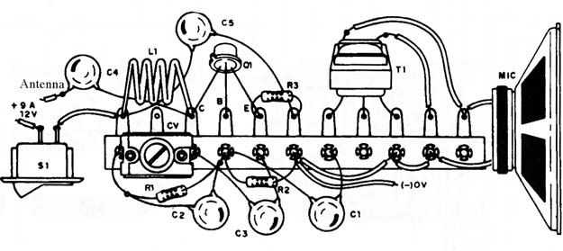
But remember that, if a terminal strip is used, a larger box will be necessary to house the circuit. Alternatively, the components can be placed on a printed circuit board as shown in Fig. 6.
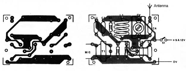
The Coil is formed by 4 or 5 tums of AWG 22 or 24 enameled wire in a 1 cm diameter form without an iron core (i.e., air core). Taps in the second or third turn can be tested for a proper antenna connection.
Any transistor audio output transformer with primary impedances rated to values between 200 and 2,000 ohm and an 8 ohm secondary winding can be used to connect the 10 ohm-impedance microphone.
. The microphone is a small transistor radio loudspeaker or any low-impedance unit (4 to 8 ohm). The antenna is a piece of solid wire (plastic covered) or a telescoping antenna as used in transistor radios with lengths in the range of 6 to 30 inches.
Adjustment and Operation
Do not power the circuit from a common 9 V battery. As the current drain is high, such a battery would fail in a few minutes.
The procedure to tune the circuit is the same as described in other transmitters of the same type in this site: place an FM receiver close to the transmitter and look for a free point in the dial.
Adjust CV to produce the strongest audio signal from the receiver. Speak into the microphone to test the modulation. If any acoustic feedback is noted, reduce the receiver volume or move it farther away from the transmitter.
Semiconductor
Q1- 2N2218 or BD135 NPN transistor (see text)
Resistors (1/8 W, 5%)
R1 - 4,700 ohm - yellow, violet, red
R2 - 2,200 ohm- red, red, red
R3 - 39 ohm - orange, white, black
Capacitors
C1 - 0.22 µF ceramic
C2 - 0.01 µF ceramic
C3, C4 - 10 pF ceramic
C5 - 0.1 µF ceramic
CV trimmer (see text)
Additional Parts and Materials
T1 - audio output transformer, 1,000 ohm x 8 ohm (see text)
L1 - coil (see text)
MIC - 8 ohm x 1 to 2 inches, small loudspeaker
S1 - SPST toggle or slide switch
B1 - 9 to 12 V, AA cells or nicad battery
Printed circuit board or terminal strip, plastic box, antenna, battery holder, wires, solder, etc.