Note: this article was originally published in a Brazilian magazine and them translated to be part o my book Prate Radio and Video pubished by Newnes in 2001.
Features
Power supply voltage: 9 to 12 Vdc
Output power: 500 mW to 2 W
Frequency range: 3 to 10 MHz
Number of transistors: 1
This project is intended for beginners and students who are looking for a circuit for conducting experiments in shortwave transmission. The circuit is simple and has no critical parts, so it can use a terminal strip as its chassis.
Because the shortwave range is less congested during daylight hours, this is the best time to locate a free point in the band for the operation of this device.
Obviously, this transmitter requires you to have access to a shortwave receiver for it to be of any use.
The modulation can be created by any small audio amplifier. The reader can use the circuit with any audio source, including an electret microphone and other types of microphones and transducers.
It is also important to remind the reader that, if an external antenna is used, the signal can carry over long distances. This means that legal restrictions on its operation must be carefully observed. For experimental purposes, the reader must use only the recommended antenna.
How It Works
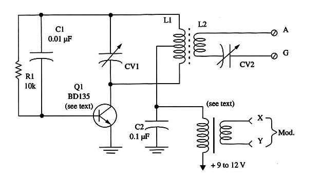
The transistor is wired as a Hartley oscillator running at a frequency determined by L1 and CV1. The circuit can be tuned by CV1 to a free point in the shortwave band between 3 and 10 MHz.
The feedback necessary to keep the oscillator running is given by C1. R1 wired in parallel with C1 is used to bias the transistor base.
To modulate this signal from an audio source, a transformer is used. One winding is used to control the power supply current, and the other to receive the audio signal.
Without any audio signal applied, the current to the circuit flows without any resistance. But, when a signal is applied, the resulting voltage controls the current flow, causing the high-frequency modulation.
Figure 1 shows how the amplitude of the high-frequency signal must change with the audio signal to achieve a correct modulation.

Notice that, in this circuit, to have a good modulation, it is necessary to use a high-power audio signal. The audio signal must have the same power as the signal produced by the transmitter.
This means that amplifiers with powers in the range between 500 mW and 2 W must be used for the external modulation.
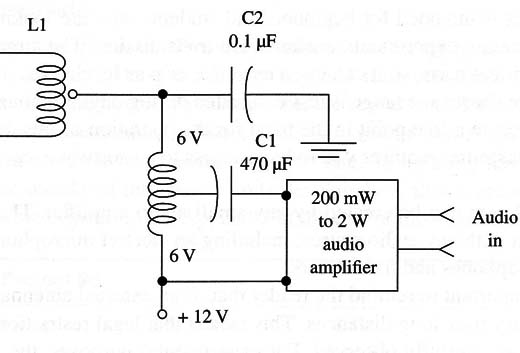
Another away to modulate this transmitter is shown in Fig. 2.

A small power supply transformer is used to control the current flowing to the transmitter.
Only the low-voltage winding is used. The applied signal acts on the current flowing and changes it, thereby altering the amplitude of the high-frequency signal produced by the Hartley oscillator.
Given that the project is experimental, we invite the reader to test several transformers with the employed modulation amplifier to find the one that gives the best performance.
The signal produced by the high-frequency oscillator and subsequently amplitude modulated is picked up from the circuit by L2. This coil, via CV2, applies the high-frequency signal to an antenna and a ground connection.
CV2 can be adjusted to match the circuit impedance, with the antenna impedance increasing the transmitter performance.
For good performance, you must use a power supply ranging from 9 to 12 V and current up to a level of 1 A. Good filtering is necessary to avoid hum.
Assembly
A schematic diagram of the shortwave transmitter is shown in Fig. 3.

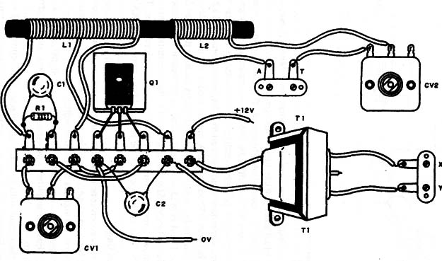
Because the project is experimental and not very critical, a terminal strip can be used as the chassis as shown in Fig. 4.

Keep all the connections short to avoid instability, and take care not to touch any component terminals to any others.
L1 is formed by 15 + 15 to 20 + 20 turns of AWG 24 to 28 enameled wire on a ferrite core 4 to 10 in. long. The diameter can be in the range between 1/4 and 1/2 in. This ferrite core can be found in any old transistor radio. L2 is formed by 10 to 12 turns using the same wire over L1.
CV1 and CV2 are small, plastic variable capacitors in the range between 120 and 360 pF.
These components can also be found in old transistor radios. But do not use FM radio parts, which have less capacitance and therefore will not work in the frequency range of interest for this project.
With the lower capacitance range, the circuit will tune only a narrow band, making adjustments difficult.
Another method of tuning the circuit is to use trimmer capacitors with capacitance ranges between 50 and 120 pF. The frequency range will be narrow, but you should be able to find it somewhere in the shortwave receiver. If not, alter the number of turns of L1 until you can tune in the signal.
The transistor must be mounted on a heat sink. This can be a small metal plate bent to form an “L” or a “U” and affixed to the component with a screw and a nut.
Any transformer with a primary winding rated to voltages between 117 Vac and 240 Vac and a secondary winding rated to voltages between 5 and 12 V, with a current rating between 250 and 800 mA, can be used as the modulation circuit.
It is also possible to use small output transformers such as the ones found in transistor radios. The 4 or 8 ohm winding is wired to the output of the modulation amplifier, and the 200 to 500 ohm winding is wired to the transmitter.
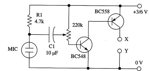
Figure 5 shows a modulation circuit using an electret microphone.

The gain is adjusted by P1. This modulator must be powered from two or four AA cells.
Adjustment and Use
Place any shortwave receiver near the transmitter and tune it to a free point in the shortwave band between 4 and 5 MHz. Use a small piece of plastic-covered wire (10 to 20 in. long) as the antenna for the transmitter.
Power on the transmitter and adjust CV1 to tune the signal. Apply a modulation signal and adjust the amplifier’s volume to get the best sound reproduction without any distortion.
When using the circuit with an external antenna, also adjust CV2 to get the best performance. Figure 6 shows an external antenna suitable for this circuit.

Notice that the antenna is a half-wave dipole, so a ground connection is not used. The best performance for the transmitter is found when the antenna dimensions correspond to half the length of the transmitted signal.
The reader can experiment with alterations in the value of R1 to get the best performance. Values between 4,700 and 22,000 ohm can be tested.
Semiconductors
Q1 - BD135, BD137, or BD139 medium-power NPN silicon transistor
Resistors (1/8 W, 5%)
R1 - 10,000 Q-brown, black, orange
Capacitors
C1 - 0.01 µF ceramic
C2 -0.1 µF ceramic
CV1, CV2 - variables (see text)
Additional Parts and Materials
L1, L2 - coils (see text)
T1 - modulation transformer (see text)
Terminal strip, power supply, plastic box, knobs for the variable capacitors, audio source, wires, solder, etc.


