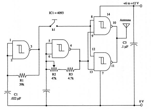
The circuit will oscillate in frequencies up to 1 MHz, and modulation is fixed within about 1 kHz. You can alter the modulation range by adding a potentiometer and a series resistor in place of R1.
A 100,000 0 potentiometer and a 10,000 Q resistor produce modulation signals in the range between 100 and 1,000 Hz. Capacitor C1 can also be altered to change this modulation frequency.
The circuit can be powered by batteries, as the drained current is very low (only a few milliamperes), extending the power supply life.
As a coil-less circuit, the frequency adjustment is made by a potentiometer.
The antenna is a wire 1 to 6 feet in length.
A schematic diagram of the transmitter is shown in Fig. 1.

For the Morse key, the reader can use the same device as described in CBV159E.
The operating frequency is adjusted by R2.
IC1 - 4093B CMOS integrated circuit
K1 - Morse key (see text)
R1 - 39,000 ohm, 1/4 W, 5% resistor
R2- 47,000 ohm potentiometer
R3 - 4,700 ohm, 1/4 W, 5% resistor
C1 - 0.022 µF ceramic or metal film capacitor
C2 - 120 pF ceramic capacitor
C3 - 0.1 µF ceramic or metal film capacitor


